Information injection-pump assembly
BOSCH
9 400 610 577
9400610577
ZEXEL
101602-2850
1016022850

Rating:
Service parts 101602-2850 INJECTION-PUMP ASSEMBLY:
1.
_
5.
AUTOM. ADVANCE MECHANIS
7.
COUPLING PLATE
8.
_
9.
_
11.
Nozzle and Holder
23600-2900A
12.
Open Pre:MPa(Kqf/cm2)
17.7{180}/21.6{220}
14.
NOZZLE
Cross reference number
BOSCH
9 400 610 577
9400610577
ZEXEL
101602-2850
1016022850
Zexel num
Bosch num
Firm num
Name
Calibration Data:
Adjustment conditions
Test oil
1404 Test oil ISO4113 or {SAEJ967d}
1404 Test oil ISO4113 or {SAEJ967d}
Test oil temperature
degC
40
40
45
Nozzle and nozzle holder
105780-8140
Bosch type code
EF8511/9A
Nozzle
105780-0000
Bosch type code
DN12SD12T
Nozzle holder
105780-2080
Bosch type code
EF8511/9
Opening pressure
MPa
17.2
Opening pressure
kgf/cm2
175
Injection pipe
Outer diameter - inner diameter - length (mm) mm 6-2-600
Outer diameter - inner diameter - length (mm) mm 6-2-600
Overflow valve
134424-0920
Overflow valve opening pressure
kPa
162
147
177
Overflow valve opening pressure
kgf/cm2
1.65
1.5
1.8
Tester oil delivery pressure
kPa
157
157
157
Tester oil delivery pressure
kgf/cm2
1.6
1.6
1.6
Direction of rotation (viewed from drive side)
Right R
Right R
Injection timing adjustment
Direction of rotation (viewed from drive side)
Right R
Right R
Injection order
1-4-2-6-
3-5
Pre-stroke
mm
4.8
4.77
4.83
Beginning of injection position
Drive side NO.1
Drive side NO.1
Difference between angles 1
Cal 1-4 deg. 60 59.75 60.25
Cal 1-4 deg. 60 59.75 60.25
Difference between angles 2
Cyl.1-2 deg. 120 119.75 120.25
Cyl.1-2 deg. 120 119.75 120.25
Difference between angles 3
Cal 1-6 deg. 180 179.75 180.25
Cal 1-6 deg. 180 179.75 180.25
Difference between angles 4
Cal 1-3 deg. 240 239.75 240.25
Cal 1-3 deg. 240 239.75 240.25
Difference between angles 5
Cal 1-5 deg. 300 299.75 300.25
Cal 1-5 deg. 300 299.75 300.25
Injection quantity adjustment
Adjusting point
A
Rack position
10.1
Pump speed
r/min
900
900
900
Average injection quantity
mm3/st.
117
116
118
Max. variation between cylinders
%
0
-3.5
3.5
Basic
*
Fixing the lever
*
Injection quantity adjustment_02
Adjusting point
-
Rack position
7.3+-0.5
Pump speed
r/min
490
490
490
Average injection quantity
mm3/st.
10
9
11
Max. variation between cylinders
%
0
-10
10
Fixing the rack
*
Remarks
Adjust only variation between cylinders; adjust governor according to governor specifications.
Adjust only variation between cylinders; adjust governor according to governor specifications.
Injection quantity adjustment_03
Adjusting point
D
Rack position
-
Pump speed
r/min
100
100
100
Average injection quantity
mm3/st.
125
125
135
Fixing the lever
*
Test data Ex:
Governor adjustment
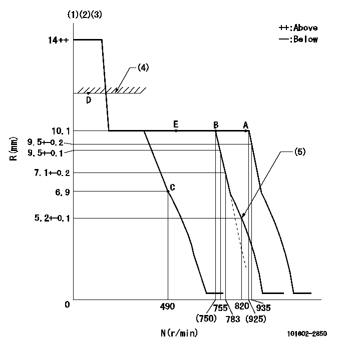
N:Pump speed
R:Rack position (mm)
(1)Target notch: K
(2)Tolerance for racks not indicated: +-0.05mm.
(3)The torque control spring does not operate.
(4)RACK LIMIT
(5)Set idle sub-spring
----------
K=8
----------
----------
K=8
----------
Speed control lever angle
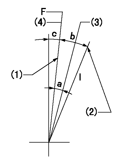
F:Full speed
I:Idle
(1)Stopper bolt setting
(2)Stopper bolt setting
(3)When pump speed set at aa
(4)Set the pump speed at bb.
----------
aa=755r/min bb=935r/min
----------
a=6deg+-5deg b=16deg+-5deg c=1deg+-5deg
----------
aa=755r/min bb=935r/min
----------
a=6deg+-5deg b=16deg+-5deg c=1deg+-5deg
Stop lever angle
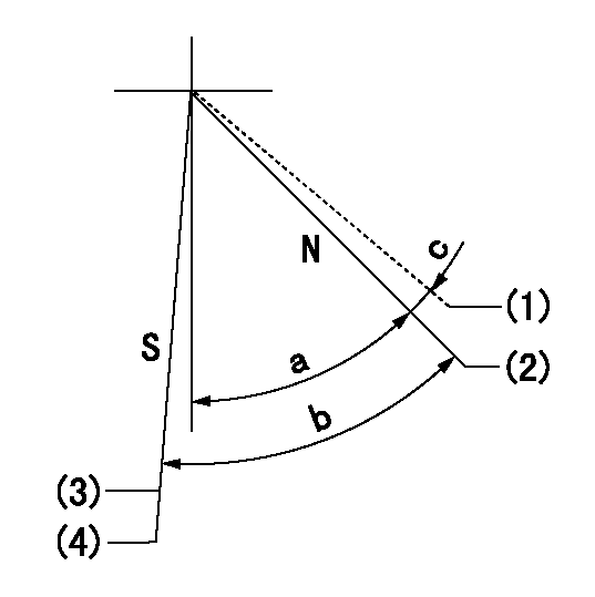
N:Pump normal
S:Stop the pump.
(1)Contacts normal side pin
(2)Distance from normal side pin = aa.
(3)At delivery
(4)Rack position = bb or less, speed = cc
----------
aa=2.5+-0.5mm bb=6.4mm cc=0r/min
----------
a=51deg+-5deg b=53deg+-5deg c=(6deg)
----------
aa=2.5+-0.5mm bb=6.4mm cc=0r/min
----------
a=51deg+-5deg b=53deg+-5deg c=(6deg)
Timing setting

(1)Pump vertical direction
(2)Coupling's key groove position at No 1 cylinder's beginning of injection
(3)-
(4)-
----------
----------
a=(50deg)
----------
----------
a=(50deg)
Information:
Table 4
Ethylene Glycol Concentration
Concentration Freeze Protection Boil Protection(1)
20 Percent −8° C (18° F) 102° C (216° F)
50 Percent −37 °C (−34 °F) 106 °C (223 °F)
60 Percent −52 °C (−62 °F) 111 °C (232 °F)
(1) Boiling protection is increased with the use of a pressurized radiator.Do not use propylene glycol in concentrations that exceed 50 percent glycol because of the reduced heat transfer capability. Use ethylene glycol in conditions that require additional protection against boiling or freezing. Do not use ethylene glycol in concentrations that exceed 60 percent glycol.
Table 5
Propylene Glycol Concentration
Concentration Freeze Protection Boil Protection(1)
50 Percent −32 °C (−26 °F) 106 °C (223 °F)
(1) Boiling protection is increased with the use of a pressurized radiator.Propylene glycol coolant that is used in the cooling systems for Cat diesel engines must meet ASTM D6210-06, "Fully-Formulated Glycol-Based Engine Coolant for Heavy-Duty Engines". When propylene glycol coolant is used in heavy-duty diesel engines, a regular addition of SCA is required for protection against liner cavitation. Consult your Cat dealer for additional information.Ethylene or propylene glycols used in cooling systems for Cat diesel engines must meet ASTM E1177-06, "Standard Specification for Engine Coolant Grade Glycol".Testing the Concentration of Glycol
To check the concentration of glycol, use the 245-5829 Coolant/Battery Tester/Refractometer or 360-0774 refractometer. The tester can be used with ethylene or propylene glycol.
Illustration 1 g01189253
Approximate curve of the freezing point for a typical ethylene glycol solution.
Table 6
Freeze Protection for Antifreeze Concentrations(1)
Protection to: Concentration
−8° C (18° F) 20% glycol
80% water
−15 °C (5 °F) 30% glycol
70% water
−24 °C (−12 °F) 40% glycol
60% water
−37 °C (−34 °F) 50% glycol
50% water
−52 °C (−62 °F) 60% glycol
40% water
(1) Ethylene glycol-based antifreeze.Alternative products that are used to protect from boiling or freezing of the engine coolant include:
“1,3 propandiol” (PDO)
glycerin
mixtures of these alternative products with glycolAt the time of publication of this document, there currently exists no ASTM, "specifications" for coolants using these chemicals. Until specifications are published and then evaluated by Cat, use of PDO and glycerin or glycerin/glycol coolants are not recommended in Cat cooling systems.Embitterment
Ethylene glycol is a toxic chemical with a naturally sweet taste. In order to avoid accidental excessive ingestion by humans or animals, coolants may contain embittering agents that make the coolant taste bad. All Cat glycol containing coolants (Cat ELC, Cat DEAC, and Cat NGEC) are embittered. Embittering agents have no beneficial or detrimental effect on coolant performance or characteristics.Coolant Terminology
Extended Life Coolant (ELC) - A coolant that relies largely on organic inhibitors for corrosion and cavitation protection. Carboxylate is an example of organic corrosion and cavitation inhibitors. Cat ELC and Cat ELI in water are extended life coolants that also include nitrites and molybdates for increased cavitation protection.
Commercial extended life coolants containing silicate do not meet the additional requirements set in this Special Publication for coolants claiming to meet Cat EC-1 specification.
Do not use commercial extended life coolants with more than 125 ppm silicon (present in the coolant in the form of silicate)
Extended life coolants that meet