Information injection-pump assembly
BOSCH
9 400 611 583
9400611583
ZEXEL
101602-2844
1016022844
HINO
220204770C
220204770c
Rating:
Service parts 101602-2844 INJECTION-PUMP ASSEMBLY:
1.
_
5.
AUTOM. ADVANCE MECHANIS
6.
COUPLING PLATE
8.
_
9.
_
11.
Nozzle and Holder
23600-2142A
12.
Open Pre:MPa(Kqf/cm2)
19.6{200}
15.
NOZZLE SET
Cross reference number
BOSCH
9 400 611 583
9400611583
ZEXEL
101602-2844
1016022844
HINO
220204770C
220204770c
Zexel num
Bosch num
Firm num
Name
101602-2844
9 400 611 583
220204770C HINO
INJECTION-PUMP ASSEMBLY
W06E-H K 14BE INJECTION PUMP ASSY PE6A PE
W06E-H K 14BE INJECTION PUMP ASSY PE6A PE
Calibration Data:
Adjustment conditions
Test oil
1404 Test oil ISO4113 or {SEJ967d}
1404 Test oil ISO4113 or {SEJ967d}
Test oil temperature
degC
40
40
45
Nozzle and nozzle holder
105780-8140
Bosch type code
EF8511/9A
Nozzle
105780-0000
Bosch type code
DN12SD12T
Nozzle holder
105780-2080
Bosch type code
EF8511/9
Opening pressure
MPa
17.2
Opening pressure
kgf/cm2
175
Injection pipe
Outer diameter - inner diameter - length (mm) mm 6-2-600
Outer diameter - inner diameter - length (mm) mm 6-2-600
Overflow valve
134424-0920
Overflow valve opening pressure
kPa
162
147
177
Overflow valve opening pressure
kgf/cm2
1.65
1.5
1.8
Tester oil delivery pressure
kPa
157
157
157
Tester oil delivery pressure
kgf/cm2
1.6
1.6
1.6
Direction of rotation (viewed from drive side)
Right R
Right R
Injection timing adjustment
Direction of rotation (viewed from drive side)
Right R
Right R
Injection order
1-4-2-6-
3-5
Pre-stroke
mm
3.45
3.42
3.48
Beginning of injection position
Drive side NO.1
Drive side NO.1
Difference between angles 1
Cal 1-4 deg. 60 59.75 60.25
Cal 1-4 deg. 60 59.75 60.25
Difference between angles 2
Cyl.1-2 deg. 120 119.75 120.25
Cyl.1-2 deg. 120 119.75 120.25
Difference between angles 3
Cal 1-6 deg. 180 179.75 180.25
Cal 1-6 deg. 180 179.75 180.25
Difference between angles 4
Cal 1-3 deg. 240 239.75 240.25
Cal 1-3 deg. 240 239.75 240.25
Difference between angles 5
Cal 1-5 deg. 300 299.75 300.25
Cal 1-5 deg. 300 299.75 300.25
Injection quantity adjustment
Adjusting point
A
Rack position
10
Pump speed
r/min
900
900
900
Average injection quantity
mm3/st.
47.9
45.9
49.9
Max. variation between cylinders
%
0
-3
3
Basic
*
Fixing the rack
*
Injection quantity adjustment_02
Adjusting point
C
Rack position
7.5+-0.5
Pump speed
r/min
450
450
450
Average injection quantity
mm3/st.
9
7.5
10.5
Max. variation between cylinders
%
0
-15
15
Fixing the rack
*
Injection quantity adjustment_03
Adjusting point
D
Rack position
-
Pump speed
r/min
100
100
100
Average injection quantity
mm3/st.
75
75
85
Fixing the lever
*
Rack limit
*
Test data Ex:
Governor adjustment
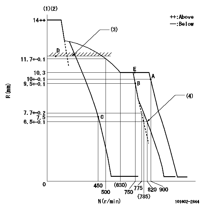
N:Pump speed
R:Rack position (mm)
(1)Target notch: K
(2)Tolerance for racks not indicated: +-0.05mm.
(3)RACK LIMIT
(4)Set idle sub-spring
----------
K=11
----------
----------
K=11
----------
Speed control lever angle
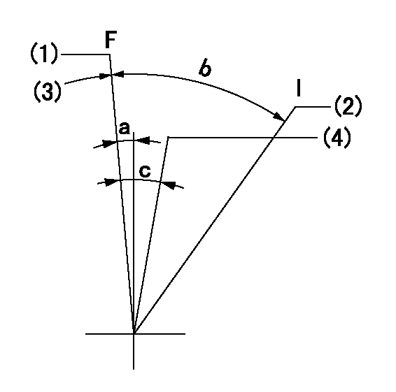
F:Full speed
I:Idle
(1)Set the pump speed at aa
(2)Stopper bolt setting
(3)Stopper bolt setting
(4)When pump speed set at bb
----------
aa=900r/min bb=750r/min
----------
a=2deg+-5deg b=19deg+-5deg c=5deg+-5deg
----------
aa=900r/min bb=750r/min
----------
a=2deg+-5deg b=19deg+-5deg c=5deg+-5deg
Stop lever angle
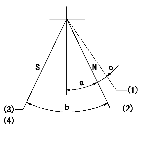
N:Pump normal
S:Stop the pump.
(1)Contacts normal side pin
(2)Distance from normal side pin = aa.
(3)At delivery
(4)Rack position = bb or less, speed = cc
----------
aa=2.5+-0.5mm bb=7mm cc=0r/min
----------
a=27deg+-5deg b=53deg+-5deg c=(6deg)
----------
aa=2.5+-0.5mm bb=7mm cc=0r/min
----------
a=27deg+-5deg b=53deg+-5deg c=(6deg)
Timing setting

(1)Pump vertical direction
(2)Position of gear's standard threaded hole at No 1 cylinder's beginning of injection
(3)-
(4)-
----------
----------
a=(70deg)
----------
----------
a=(70deg)
Information:
When referring to the Service Life in table 1, use the interval that occurs first. These coolant change intervals are only achievable with annual S O S Services Level 2 coolant sampling analysis.Refer to the engine Operation and Maintenance Manual for the correct interval for replacement of the cooling system water temperature regulator.Note: For engines that require a maximum of 20% glycol, make sure that the amount of additive in the final mix is appropriate. Example of mixing a 20% glycol solution is given in Table 3.
Table 3
Example of Mixing Up a 20% Glycol Coolant (1)
Total Volume of the Cooling System Add the Following:
ELC Concentrate ELI Concentrate Water
10 Gallons 2 Gallons 0.5 Gallons 7.5 Gallons
(1) Volumes can also be in liters as long as all the volume units are consistentExtended life coolants require the one time maintenance addition of an extender at coolant service mid-life. For commercial coolants, do NOT use an extender with a coolant unless the extender has been approved by the coolant manufacturer for use with the coolant. The coolant manufacturer is responsible to ensure compatibility and acceptable performance. Failure to follow these recommendations can result in shortened cooling system component life.Conventional coolants require the maintenance addition of SCA throughout the expected life. For commercial coolants, do NOT use an SCA unless approved by the coolant supplier for use with the coolant. The coolant manufacturer is responsible to ensure compatibility and acceptable performance."ASTM D4985" and "ASTM D6210" require coolants that are properly dosed with SCA and that are in a properly maintained cooling system in normal service to be suitable for use for a maximum of 1 year ("ASTM D4985") and 2 years ("ASTM D6210"). The suitability for use requirement is the direct responsibility of the coolant manufacturer and SCA manufacturer. Consult with the coolant and/or SCA manufacturer concerning the suitability of the products for use in a given application.Cat DEAC does not require a treatment with an SCA at the initial fill.A commercial heavy-duty coolant/antifreeze that meets the "ASTM D6210"specification does not require a treatment with an SCA at the initial fill.A commercial heavy-duty coolant/antifreeze that only meets "ASTM D4985", WILL require a treatment with an SCA at the initial fill and has to fulfill all the requirements listed in the “Technical Requirements for Commercial Extended Life Coolants” table. The
Have questions with 101602-2844?
Group cross 101602-2844 ZEXEL
Hino
Hino
101602-2844
9 400 611 583
220204770C
INJECTION-PUMP ASSEMBLY
W06E-H
W06E-H