Information injection-pump assembly
BOSCH
9 400 619 550
9400619550
ZEXEL
101602-2841
1016022841
HINO
220204770B
220204770b
Rating:
Service parts 101602-2841 INJECTION-PUMP ASSEMBLY:
1.
_
5.
AUTOM. ADVANCE MECHANIS
6.
COUPLING PLATE
8.
_
9.
_
11.
Nozzle and Holder
12.
Open Pre:MPa(Kqf/cm2)
19.6{200}
15.
NOZZLE SET
Cross reference number
BOSCH
9 400 619 550
9400619550
ZEXEL
101602-2841
1016022841
HINO
220204770B
220204770b
Zexel num
Bosch num
Firm num
Name
9 400 619 550
220204770B HINO
INJECTION-PUMP ASSEMBLY
W06E-H * K 14BE PE6A PE
W06E-H * K 14BE PE6A PE
Calibration Data:
Adjustment conditions
Test oil
1404 Test oil ISO4113 or {SAEJ967d}
1404 Test oil ISO4113 or {SAEJ967d}
Test oil temperature
degC
40
40
45
Nozzle and nozzle holder
105780-8140
Bosch type code
EF8511/9A
Nozzle
105780-0000
Bosch type code
DN12SD12T
Nozzle holder
105780-2080
Bosch type code
EF8511/9
Opening pressure
MPa
17.2
Opening pressure
kgf/cm2
175
Injection pipe
Outer diameter - inner diameter - length (mm) mm 6-2-600
Outer diameter - inner diameter - length (mm) mm 6-2-600
Overflow valve
134424-0920
Overflow valve opening pressure
kPa
162
147
177
Overflow valve opening pressure
kgf/cm2
1.65
1.5
1.8
Tester oil delivery pressure
kPa
157
157
157
Tester oil delivery pressure
kgf/cm2
1.6
1.6
1.6
Direction of rotation (viewed from drive side)
Right R
Right R
Injection timing adjustment
Direction of rotation (viewed from drive side)
Right R
Right R
Injection order
1-4-2-6-
3-5
Pre-stroke
mm
3.45
3.42
3.48
Beginning of injection position
Drive side NO.1
Drive side NO.1
Difference between angles 1
Cal 1-4 deg. 60 59.75 60.25
Cal 1-4 deg. 60 59.75 60.25
Difference between angles 2
Cyl.1-2 deg. 120 119.75 120.25
Cyl.1-2 deg. 120 119.75 120.25
Difference between angles 3
Cal 1-6 deg. 180 179.75 180.25
Cal 1-6 deg. 180 179.75 180.25
Difference between angles 4
Cal 1-3 deg. 240 239.75 240.25
Cal 1-3 deg. 240 239.75 240.25
Difference between angles 5
Cal 1-5 deg. 300 299.75 300.25
Cal 1-5 deg. 300 299.75 300.25
Injection quantity adjustment
Adjusting point
A
Rack position
10
Pump speed
r/min
900
900
900
Average injection quantity
mm3/st.
47.9
45.9
49.9
Max. variation between cylinders
%
0
-3
3
Basic
*
Fixing the rack
*
Injection quantity adjustment_02
Adjusting point
C
Rack position
7.5+-0.5
Pump speed
r/min
450
450
450
Average injection quantity
mm3/st.
9
7.5
10.5
Max. variation between cylinders
%
0
-15
15
Fixing the rack
*
Injection quantity adjustment_03
Adjusting point
D
Rack position
-
Pump speed
r/min
100
100
100
Average injection quantity
mm3/st.
75
75
85
Fixing the lever
*
Rack limit
*
Test data Ex:
Governor adjustment
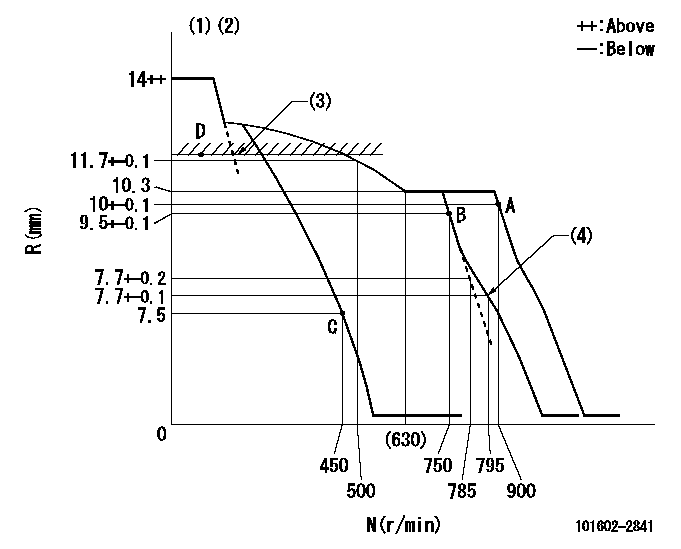
N:Pump speed
R:Rack position (mm)
(1)Target notch: K
(2)Tolerance for racks not indicated: +-0.05mm.
(3)RACK LIMIT
(4)Set idle sub-spring
----------
K=15
----------
----------
K=15
----------
Speed control lever angle
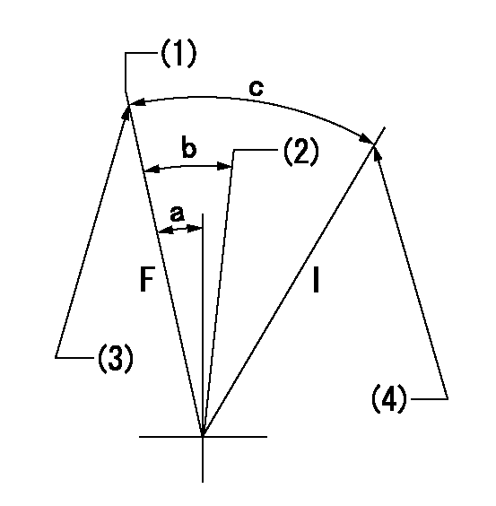
F:Full speed
I:Idle
(1)Set the pump speed at aa
(2)When pump speed set at bb
(3)Stopper bolt setting
(4)Stopper bolt setting
----------
aa=900r/min bb=750r/min
----------
a=4deg+-5deg b=5deg+-5deg c=19deg+-5deg
----------
aa=900r/min bb=750r/min
----------
a=4deg+-5deg b=5deg+-5deg c=19deg+-5deg
Stop lever angle

N:Pump normal
S:Stop the pump.
(1)Distance from normal side pin = aa.
(2)At shipping: rack position = bb or less, speed = cc.
(3)Contacts normal side pin
----------
aa=2.5+-0.5mm bb=7mm cc=0r/min
----------
a=27deg+-5deg b=53deg+-5deg c=(6deg)
----------
aa=2.5+-0.5mm bb=7mm cc=0r/min
----------
a=27deg+-5deg b=53deg+-5deg c=(6deg)
Timing setting

(1)Pump vertical direction
(2)Position of gear's standard threaded hole at No 1 cylinder's beginning of injection
(3)-
(4)-
----------
----------
a=(70deg)
----------
----------
a=(70deg)
Information:
Table 1
Features Benefits
All engineering changes and updates included Improved reliability and performance
Worldwide availability through the Cat® Parts Distribution System Customer access regardless of location
Off the shelf reliability Downtime reduced through exchanged product
Same as new Caterpillar warranty Consistent support
Illustration 1 g06211468
(1) Rocker arm with MEUI-A hardware
(2) Rocker arm with MEUI-C hardware
Table 2
MEUI-A Rocker MEUI-C Rocker
258-8721 Button 192-4151 Button
274-4492 Arm Adjustment Screw 196-5069 Arm Adjustment Screw
8L-2777 O-Ring Seal 061-8639 O-Ring Seal
Table 3
Reman Part Number New Part Number Engine Serial Number Prefixes
20R-3319 437-3881 115, 127, 132, 137, 173, 174, 175, 2A3, 3LW, 5DS, 7CZ, 8AZ, 9NN, 9YP, AL6, AN2, AR2, AR3, ASW, AT4, AZW, B2C, B3G, BEM, BFM, BGA, BXS, C1G, C2T, C4G, C5E, C5L, C6C, CAH, CCB, CE5, CKH, CWJ, DCT, DDS, DGK, DGL, DKE, DSJ, DWB, E1Y, GB3, GBM, GDS, GEN, GES, GRS, GSZ, GTB, HAZ, J2K, JAZ, JCF, JDA, JE9, JHL, JKG, JKS, JNZ, JSJ, K7C, KJT, KNM, KRA, L8D, LNA, LWR, LXJ, LXK, M1W, M1Y, M1Z, M7W, MCW, MDP, MED, MG2, MPE, MXS, N5F, NAW, NAY, NB2, NEW, NKL, NRC, NXS, P8B, PBL, PCY, PCZ, PEC, PEE, PEF, PEJ, PEK, PET, PHT, PHW, PKG, PKY, PKZ, R8W, RAM, RET, RGX, RLA, RNE, RNF, RNR, RNX, RNY, RNZ, RPM, RSD, RTK, S1P, SDN, SDP, SMP, SNW, SSM, STG, SXC, T3T, T4A, TG7, THS, TLD, TNA, TWM, W1A, WJB, WJY, WKB, X5M, XMJ, ZAG, ZKA, ZKB, ZP3, XP5
20R-3322 437-3862 176, 188, 1LW, 1MM, 2WS, 4AS, 5EK, 6BR, 6TB, 6TG, 6TS, 7T2, 9BZ, 9WR, B5R, BDN, BG4, BP2, BS9, C1J, C2A, C3G, C5H, CBX, CJP, CYN, CYY, DPG, DTP, DZE, EGH, EJG, EKW, EPE, F5C, F8N, G4C, GEX, GHJ, GJE, JAS, JDK, JDY, JEP, JKX, JLE, JRE, JWH, JZB, KCM, KEM, L8B, LDN, LET, LNB, LZA, LZB, MBN, MEP, MGS, MMB, N1C, N1D, NAP, NAX, NBB, NKK, PBN, PDM, PGN, PLE, RKS, RNC, RRC, RT2, RWS, SAY, SSW, STD, STM, SWE, T2P, T2R, TRB, WJA, WJH, WJW, WRH, X4R, XMK, Z2C, ZAY