Information injection-pump assembly
ZEXEL
101602-2840
1016022840
HINO
220204770A
220204770a
Rating:
Service parts 101602-2840 INJECTION-PUMP ASSEMBLY:
1.
_
5.
AUTOM. ADVANCE MECHANIS
6.
COUPLING PLATE
8.
_
9.
_
11.
Nozzle and Holder
23600-2142A
12.
Open Pre:MPa(Kqf/cm2)
19.6{200}
15.
NOZZLE SET
Cross reference number
ZEXEL
101602-2840
1016022840
HINO
220204770A
220204770a
Zexel num
Bosch num
Firm num
Name
Calibration Data:
Adjustment conditions
Test oil
1404 Test oil ISO4113 or {SAEJ967d}
1404 Test oil ISO4113 or {SAEJ967d}
Test oil temperature
degC
40
40
45
Nozzle and nozzle holder
105780-8140
Bosch type code
EF8511/9A
Nozzle
105780-0000
Bosch type code
DN12SD12T
Nozzle holder
105780-2080
Bosch type code
EF8511/9
Opening pressure
MPa
17.2
Opening pressure
kgf/cm2
175
Injection pipe
Outer diameter - inner diameter - length (mm) mm 6-2-600
Outer diameter - inner diameter - length (mm) mm 6-2-600
Overflow valve
134424-0920
Overflow valve opening pressure
kPa
162
147
177
Overflow valve opening pressure
kgf/cm2
1.65
1.5
1.8
Tester oil delivery pressure
kPa
157
157
157
Tester oil delivery pressure
kgf/cm2
1.6
1.6
1.6
Direction of rotation (viewed from drive side)
Right R
Right R
Injection timing adjustment
Direction of rotation (viewed from drive side)
Right R
Right R
Injection order
1-4-2-6-
3-5
Pre-stroke
mm
3.45
3.42
3.48
Beginning of injection position
Drive side NO.1
Drive side NO.1
Difference between angles 1
Cal 1-4 deg. 60 59.75 60.25
Cal 1-4 deg. 60 59.75 60.25
Difference between angles 2
Cyl.1-2 deg. 120 119.75 120.25
Cyl.1-2 deg. 120 119.75 120.25
Difference between angles 3
Cal 1-6 deg. 180 179.75 180.25
Cal 1-6 deg. 180 179.75 180.25
Difference between angles 4
Cal 1-3 deg. 240 239.75 240.25
Cal 1-3 deg. 240 239.75 240.25
Difference between angles 5
Cal 1-5 deg. 300 299.75 300.25
Cal 1-5 deg. 300 299.75 300.25
Injection quantity adjustment
Adjusting point
A
Rack position
10
Pump speed
r/min
900
900
900
Average injection quantity
mm3/st.
47.9
45.9
49.9
Max. variation between cylinders
%
0
-3
3
Basic
*
Fixing the rack
*
Injection quantity adjustment_02
Adjusting point
C
Rack position
7.5+-0.5
Pump speed
r/min
450
450
450
Average injection quantity
mm3/st.
9
7.5
10.5
Max. variation between cylinders
%
0
-15
15
Fixing the rack
*
Injection quantity adjustment_03
Adjusting point
D
Rack position
-
Pump speed
r/min
100
100
100
Average injection quantity
mm3/st.
75
75
85
Fixing the lever
*
Rack limit
*
Test data Ex:
Governor adjustment
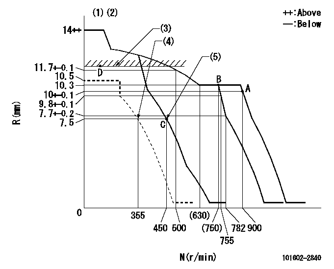
N:Pump speed
R:Rack position (mm)
(1)Target notch: K
(2)Tolerance for racks not indicated: +-0.05mm.
(3)RACK LIMIT
(4)Set idle sub-spring
(5)Main spring setting
----------
K=9
----------
----------
K=9
----------
Speed control lever angle
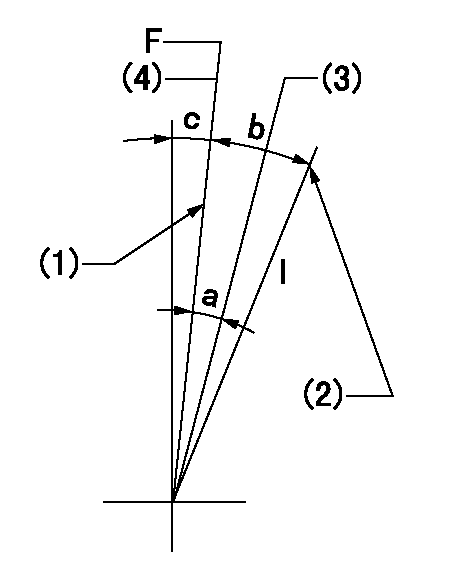
F:Full speed
I:Idle
(1)Stopper bolt setting
(2)Stopper bolt setting
(3)When pump speed set at aa
(4)Set the pump speed at bb.
----------
aa=755r/min bb=900r/min
----------
a=5deg+-5deg b=18deg+-5deg c=1deg+-5deg
----------
aa=755r/min bb=900r/min
----------
a=5deg+-5deg b=18deg+-5deg c=1deg+-5deg
Stop lever angle

N:Pump normal
S:Stop the pump.
(1)Distance from normal side pin = aa.
(2)At shipping: rack position = bb or less, speed = cc.
(3)Contacts normal side pin
----------
aa=2.5+-0.5mm bb=7mm cc=0r/min
----------
a=27deg+-5deg b=53deg+-5deg c=(6deg)
----------
aa=2.5+-0.5mm bb=7mm cc=0r/min
----------
a=27deg+-5deg b=53deg+-5deg c=(6deg)
Timing setting

(1)Pump vertical direction
(2)Position of gear's standard threaded hole at No 1 cylinder's beginning of injection
(3)-
(4)-
----------
----------
a=(70deg)
----------
----------
a=(70deg)
Information:
Machine Preparation
Prepare the machine for maintenance.Refer to Operation and Maintenance Manual, SEBU8491, "Prepare the Machine for Maintenance".Removal Procedure
Illustration 2 g06215589
(A) 383-2040 Guard
(B) 8T-4195 Bolt
(C) 8T-4121 Hard Washer
(D) 384-0966 Insert
Remove and save the DEF guard (A), three bolts (B), three hard washers (C), and three inserts (D).
Illustration 3 g06217988
(C) 8T-4121 Hard Washer
(E) 368-4513 Side Plate
(F) 365-2227 Hose As
(G) 8T-4136 Bolt
(H) 1S-0994 Clip
(J) 8T-4137 Bolt
(K) 1S-1015 Clip
(L) 7K-1181 Cable Strap
Illustration 4 g06217851
(E) 368-4513 Side Plate
Illustration 5 g06219874
View of Area M
(C) 8T-4121 Hard Washer
(H) 1S-0994 Clip
(N) 399-3078 Machine Software Gp
(P) 434-1305 Insulation
(R) 326-4516 Cable Tie
(S) 8T-4195 Bolt
(T) 7X-7729 Washer
(U) 8T-4133 Nut
Remove six hard washers (C), two bolts (G), five clips (H), two bolts (J), clip (K), four cable straps (L), five cable ties (R), protective insulation (P), two bolts (S), two washers (T), and two nuts (U) from the hose assembly (F). Discard five clips (H), clip (K), five cable ties (R). Retain the rest of the parts.
Remove and discard hose assembly (F) from DEF tank and DEF Injector Mounting Gp (N). Refer to Illustration 3 and Illustration 5.Installation Procedure
Illustration 6 g06215872
(C) 8T-4121 Hard Washer
(G) 8T-4136 Bolt
(J) 8T-4137 Bolt
(1) 471-4171 Hose As
(2) 1S-0994 Clip
(3) 7K-1181 Cable Strap
(4) 1S-1015 Clip
Illustration 7 g06219875
View of Area M
(C) 8T-4121 Hard Washer
(N) 399-6078 DEF Injector & Mounting Gp
(P) 434-1305 Insulation
(S) 8T-4195 Bolt
(T) 7X-7729 Washer
(U) 8T-4133 Nut
(1) 471-4171 Hose As
(2) 1S-0994 Clip
(5) 326-4516 Cable Tie
Install new hose assembly (1) to the DEF tank and DEF injector mounting group (N). Secure hose assembly (1) using five clips (2), four cable straps (3), clip (4), six hard washers (C), two bolts (G), two bolts (J), two bolts (S), two washers (T), and two nuts (U) that were saved in Step 2 of Section "Removal Procedure". Refer to Illustration 6 and Illustration 7.
Secure protective insulation (P) that was saved in Step 2 of Section "Removal Procedure" to hose assembly (1) using five cable ties (5). Refer to Illustration 7.
Illustration 8 g06215593
(A) 383-2040 Guard
(V) Template
Illustration 9 g06215595
(X) 94.4 mm (3.72 inch)
(Y) 225 mm (8.9 inch)
Use Illustration 9 as a template and position the template onto guard (A), aligning to the edges. Trim the guard (A) according to the template. Refer to Illustration 8.Note: Lay the template flat on the guard. The trimmed area of the guard (A) is the curved area. The square cutout on the template is not to be cut, the square corner allows the template to lay flatter on the guard.
Illustration 10 g06215889
(A) 383-2040 Guard
(E) 368-4513 Side Plate
(1) 471-4171 Hose As
Install the modified DEF guard (A) using the hardware that was saved in Step 1 of Section "Removal Procedure".Note: Ensure adequate clearance has been obtained.
Return machine to service.