Information injection-pump assembly
BOSCH
9 400 614 797
9400614797
ZEXEL
101602-2790
1016022790
HINO
220204510A
220204510a
Rating:
Service parts 101602-2790 INJECTION-PUMP ASSEMBLY:
1.
_
5.
AUTOM. ADVANCE MECHANIS
6.
COUPLING PLATE
8.
_
9.
_
11.
Nozzle and Holder
23600-1710
12.
Open Pre:MPa(Kqf/cm2)
21.6{220}
15.
NOZZLE SET
Cross reference number
BOSCH
9 400 614 797
9400614797
ZEXEL
101602-2790
1016022790
HINO
220204510A
220204510a
Zexel num
Bosch num
Firm num
Name
101602-2790
9 400 614 797
220204510A HINO
INJECTION-PUMP ASSEMBLY
W06D-T K
W06D-T K
101602-2790
9 400 614 797
S220204510A HINO
INJECTION-PUMP ASSEMBLY
W06D-T A K
W06D-T A K
Calibration Data:
Adjustment conditions
Test oil
1404 Test oil ISO4113 or {SAEJ967d}
1404 Test oil ISO4113 or {SAEJ967d}
Test oil temperature
degC
40
40
45
Nozzle and nozzle holder
105780-8140
Bosch type code
EF8511/9A
Nozzle
105780-0000
Bosch type code
DN12SD12T
Nozzle holder
105780-2080
Bosch type code
EF8511/9
Opening pressure
MPa
17.2
Opening pressure
kgf/cm2
175
Injection pipe
Outer diameter - inner diameter - length (mm) mm 6-2-600
Outer diameter - inner diameter - length (mm) mm 6-2-600
Overflow valve
131424-5720
Overflow valve opening pressure
kPa
255
221
289
Overflow valve opening pressure
kgf/cm2
2.6
2.25
2.95
Tester oil delivery pressure
kPa
157
157
157
Tester oil delivery pressure
kgf/cm2
1.6
1.6
1.6
Direction of rotation (viewed from drive side)
Right R
Right R
Injection timing adjustment
Direction of rotation (viewed from drive side)
Right R
Right R
Injection order
1-4-2-6-
3-5
Pre-stroke
mm
3.4
3.35
3.45
Beginning of injection position
Drive side NO.1
Drive side NO.1
Difference between angles 1
Cal 1-4 deg. 60 59.5 60.5
Cal 1-4 deg. 60 59.5 60.5
Difference between angles 2
Cyl.1-2 deg. 120 119.5 120.5
Cyl.1-2 deg. 120 119.5 120.5
Difference between angles 3
Cal 1-6 deg. 180 179.5 180.5
Cal 1-6 deg. 180 179.5 180.5
Difference between angles 4
Cal 1-3 deg. 240 239.5 240.5
Cal 1-3 deg. 240 239.5 240.5
Difference between angles 5
Cal 1-5 deg. 300 299.5 300.5
Cal 1-5 deg. 300 299.5 300.5
Injection quantity adjustment
Adjusting point
A
Rack position
10.5
Pump speed
r/min
1300
1300
1300
Average injection quantity
mm3/st.
88
86
90
Max. variation between cylinders
%
0
-3
3
Basic
*
Fixing the lever
*
Boost pressure
kPa
26.7
26.7
Boost pressure
mmHg
200
200
Injection quantity adjustment_02
Adjusting point
-
Rack position
7.6+-0.5
Pump speed
r/min
365
365
365
Average injection quantity
mm3/st.
9
7.5
10.5
Max. variation between cylinders
%
0
-15
15
Fixing the rack
*
Boost pressure
kPa
0
0
0
Boost pressure
mmHg
0
0
0
Remarks
Adjust only variation between cylinders; adjust governor according to governor specifications.
Adjust only variation between cylinders; adjust governor according to governor specifications.
Injection quantity adjustment_03
Adjusting point
E
Rack position
-
Pump speed
r/min
100
100
100
Average injection quantity
mm3/st.
98
98
108
Fixing the lever
*
Boost pressure
kPa
0
0
0
Boost pressure
mmHg
0
0
0
Rack limit
*
Boost compensator adjustment
Pump speed
r/min
600
600
600
Rack position
R1-1.2
Boost pressure
kPa
2
2
4.7
Boost pressure
mmHg
15
15
35
Boost compensator adjustment_02
Pump speed
r/min
600
600
600
Rack position
R1(10.5)
Boost pressure
kPa
13.3
13.3
13.3
Boost pressure
mmHg
100
100
100
Test data Ex:
Governor adjustment
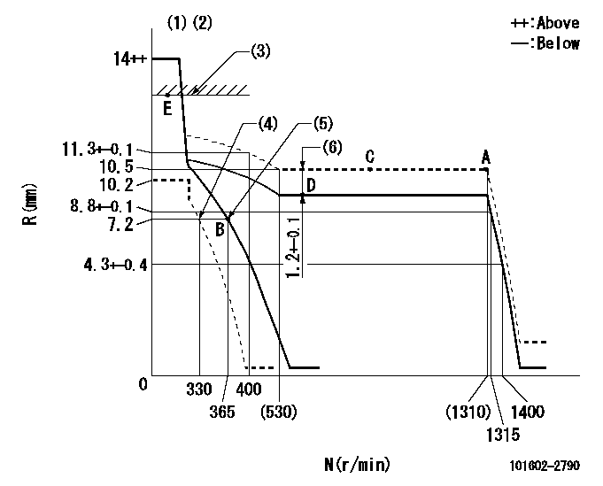
N:Pump speed
R:Rack position (mm)
(1)Target notch: K
(2)Tolerance for racks not indicated: +-0.05mm.
(3)RACK LIMIT
(4)Set idle sub-spring
(5)Main spring setting
(6)Boost compensator stroke
----------
K=5
----------
----------
K=5
----------
Speed control lever angle
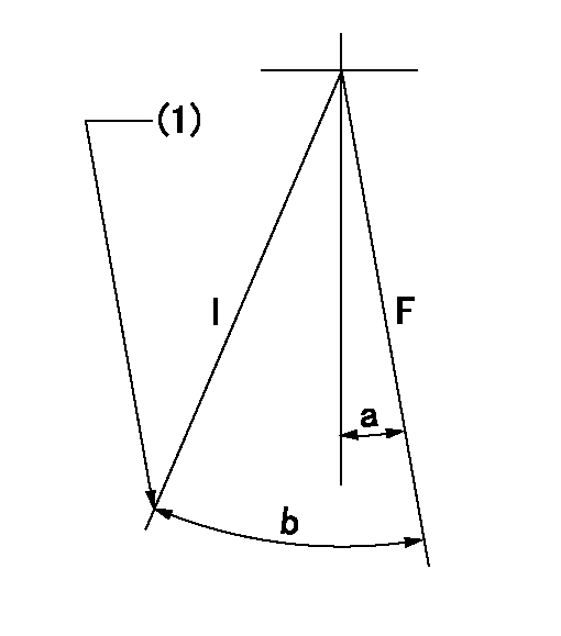
F:Full speed
I:Idle
(1)Stopper bolt setting
----------
----------
a=2deg+-5deg b=26deg+-5deg
----------
----------
a=2deg+-5deg b=26deg+-5deg
Stop lever angle

N:Pump normal
S:Stop the pump.
(1)Pump speed aa and rack position bb (to be sealed at delivery)
----------
aa=0r/min bb=1-0.2mm
----------
a=21deg+-5deg b=(55deg)
----------
aa=0r/min bb=1-0.2mm
----------
a=21deg+-5deg b=(55deg)
Timing setting

(1)Pump vertical direction
(2)Position of gear's standard threaded hole at No 1 cylinder's beginning of injection
(3)-
(4)-
----------
----------
a=(70deg)
----------
----------
a=(70deg)
Information:
Introduction
The problem that is identified below does not have a known permanent solution. Until a permanent solution is known, use the solution that is identified below.Problem
The DOC/DPF can become plugged if an NRS cooler failure occurs and coolant passes out the exhaust. Solution
If an engine has an NRS cooler failure, the DPF and DOC will need inspected for calcium deposits. In some cases calcium has partially filled the DPF and caused frequent regeneration issues, and erratic high soot loading readings.
Illustration 1 g03374496
Example of calcium deposits on DPF face
Illustration 2 g03374497
Example of calcium deposits on DPF faceThe calcium deposits will be a white and black powdery mixture on the face of the DPF and the DOC. Refer to Illustrations 1 and 2 for examples of a DPF with calcium plugging on the DPF face.Refer to Reuse And Salvage Guidelines, SEBF9223, "Inspection of Diesel Particulate Filters and Diesel Oxidation Catalysts for Tier 4 Machine and Industrial Engines" for further assistance.
Have questions with 101602-2790?
Group cross 101602-2790 ZEXEL
Hino
Hino
Hino
Hino
Hino
Hino
Hino
Hino
101602-2790
9 400 614 797
220204510A
INJECTION-PUMP ASSEMBLY
W06D-T
W06D-T
101602-2790
9 400 614 797
S220204510A
INJECTION-PUMP ASSEMBLY
W06D-T
W06D-T