Information injection-pump assembly
ZEXEL
101602-2751
1016022751
HINO
220204351A
220204351a

Rating:
Cross reference number
ZEXEL
101602-2751
1016022751
HINO
220204351A
220204351a
Zexel num
Bosch num
Firm num
Name
Calibration Data:
Adjustment conditions
Test oil
1404 Test oil ISO4113 or {SAEJ967d}
1404 Test oil ISO4113 or {SAEJ967d}
Test oil temperature
degC
40
40
45
Nozzle and nozzle holder
105780-8140
Bosch type code
EF8511/9A
Nozzle
105780-0000
Bosch type code
DN12SD12T
Nozzle holder
105780-2080
Bosch type code
EF8511/9
Opening pressure
MPa
17.2
Opening pressure
kgf/cm2
175
Injection pipe
Outer diameter - inner diameter - length (mm) mm 6-2-600
Outer diameter - inner diameter - length (mm) mm 6-2-600
Overflow valve
134424-0920
Overflow valve opening pressure
kPa
162
147
177
Overflow valve opening pressure
kgf/cm2
1.65
1.5
1.8
Tester oil delivery pressure
kPa
157
157
157
Tester oil delivery pressure
kgf/cm2
1.6
1.6
1.6
Direction of rotation (viewed from drive side)
Right R
Right R
Injection timing adjustment
Direction of rotation (viewed from drive side)
Right R
Right R
Injection order
1-4-2-6-
3-5
Pre-stroke
mm
4.4
4.35
4.45
Beginning of injection position
Drive side NO.1
Drive side NO.1
Difference between angles 1
Cal 1-4 deg. 60 59.5 60.5
Cal 1-4 deg. 60 59.5 60.5
Difference between angles 2
Cyl.1-2 deg. 120 119.5 120.5
Cyl.1-2 deg. 120 119.5 120.5
Difference between angles 3
Cal 1-6 deg. 180 179.5 180.5
Cal 1-6 deg. 180 179.5 180.5
Difference between angles 4
Cal 1-3 deg. 240 239.5 240.5
Cal 1-3 deg. 240 239.5 240.5
Difference between angles 5
Cal 1-5 deg. 300 299.5 300.5
Cal 1-5 deg. 300 299.5 300.5
Injection quantity adjustment
Adjusting point
A
Rack position
10.5
Pump speed
r/min
700
700
700
Average injection quantity
mm3/st.
80
78.5
81.5
Max. variation between cylinders
%
0
-3.5
3.5
Basic
*
Fixing the lever
*
Boost pressure
kPa
36
36
Boost pressure
mmHg
270
270
Injection quantity adjustment_02
Adjusting point
C
Rack position
6.5+-0.5
Pump speed
r/min
425
425
425
Average injection quantity
mm3/st.
8
6.5
9.5
Max. variation between cylinders
%
0
-10
10
Fixing the rack
*
Boost pressure
kPa
0
0
0
Boost pressure
mmHg
0
0
0
Boost compensator adjustment
Pump speed
r/min
700
700
700
Rack position
9.8
Boost pressure
kPa
14.7
12
17.4
Boost pressure
mmHg
110
90
130
Boost compensator adjustment_02
Pump speed
r/min
700
700
700
Rack position
10.5
Boost pressure
kPa
22.7
22.7
22.7
Boost pressure
mmHg
170
170
170
Test data Ex:
Governor adjustment
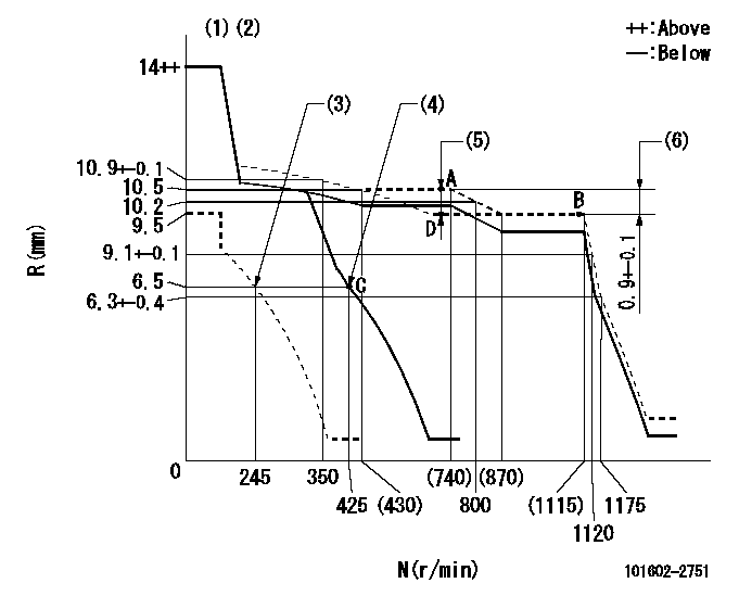
N:Pump speed
R:Rack position (mm)
(1)Target notch: K
(2)Tolerance for racks not indicated: +-0.05mm.
(3)Set idle sub-spring
(4)Main spring setting
(5)Boost compensator stroke: BCL
(6)Rack difference between N = N1 and N = N2
----------
K=11 BCL=0.7+-0.1mm N1=1100r/min N2=700r/min
----------
----------
K=11 BCL=0.7+-0.1mm N1=1100r/min N2=700r/min
----------
Speed control lever angle
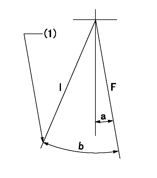
F:Full speed
I:Idle
(1)Stopper bolt setting
----------
----------
a=6deg+-5deg b=24deg+-5deg
----------
----------
a=6deg+-5deg b=24deg+-5deg
Stop lever angle

N:Pump normal
S:Stop the pump.
(1)Pump speed aa and rack position bb (to be sealed at delivery)
----------
aa=0r/min bb=1-0.2mm
----------
a=21deg+-5deg b=(55deg)
----------
aa=0r/min bb=1-0.2mm
----------
a=21deg+-5deg b=(55deg)
Timing setting

(1)Pump vertical direction
(2)Position of gear's standard threaded hole at No 1 cylinder's beginning of injection
(3)-
(4)-
----------
----------
a=(70deg)
----------
----------
a=(70deg)
Information:
Illustration 70 g03402776
Install 8T-5389 Elbow (12) using 238-5081 O-Ring Seal (11) and 228-7092 O-Ring Seal (13)
Illustration 71 g03701313
Install 6V-8636 Connector (17) using 214-7568 O-Ring Seal (16) and 228-7089 O-Ring Seal (18). Install 128-6841 Elbow (15) using 238-5082 O-Ring Seal (19) and 228-7092 O-Ring Seal (14).
Illustration 72 g03701321
Reconnect 209-5526 Hose As (20) to the fuel transfer pump
Illustration 73 g03701349
Install 387-7154 Tube As (21) and 387-7159 Tube As (22).
Illustration 74 g03701355
Install 416-9706 Fuel Tube (24) using 338-8439 Clip (23).
Install the remaining components that were removed during the HEUI pump replacement procedure.Installation Procedure for 511, 521, 522, 532, 541 and 552 Track Feller Bunchers
Table 10
Required parts for 532, 541, 541B , 551, 552, and 552B Track Feller Bunchers
Part Number Description Quantity
384-0607 Unit Injector Hydraulic Pump Gp 1
227-5904 O-Ring Seal 1
6V-7981 Bolt 2
6V-5839 Washer 2
387-7153 Tube As 1
387-7151 Tube As 1
6V-8629 Elbow 1
238-5081 O-Ring Seal 1
228-7092 O-Ring Seal 2
128-6841 Elbow 1
238-5082 O-Ring Seal 1
6V-8636 Connector 2
228-7089 O-Ring Seal 2
214-7568 O-Ring Seal 3
360-3679 Connector Plug 1
6V-3305 O-Ring Adapter 1
214-7567 O-Ring Seal 2
Illustration 75 g03402944
Install 6V-3305 O-Ring Adapter (2) using 214-7567 O-Ring Seal (1). Also install new 214-7567 O-Ring Seal (1) to injection actuation pressure sensor.
Illustration 76 g03402955
Install 384-0607 Unit Injector Hydraulic Pump Gp (4) using 227-5904 O-Ring Seal (3). If necessary, in order to aid in installation, rotate the pump to an 8 o'clock position when looking at the engine from the rear.
Illustration 77 g03402984
Install new 6V-7981 Bolts (5) and 6V-5839 Washers (6). Torque to 55 10 N m (41 7 lb ft)
Illustration 78 g03701359
Install the 6V-8636 Connector (12) using 214-7568 O-Ring Seal (11) and 228-7089 O-Ring Seal (13). Install 360-3679 Connector Plug (10) using 214-7568 O-Ring Seal (11). Install 6V-8629 Elbow (8) using 238-5081 O-Ring Seal (7) and 228-7092 O-Ring Seal (9).
Illustration 79 g03701379
Install 128-6841 Elbow (15) using 238-5082 O-Ring Seal (19) and 228-7092 O-Ring Seal (14). Install 6V-8636 Connector (17) using 214-7568 O-Ring Seal (16) and 228-7089 O-Ring Seal (18).
Illustration 80 g03701406
Install 387-7151 Tube As (21) and 387-7153 Tube As (20).
Install the remaining components that were removed during the HEUI pump replacement procedure.