Information injection-pump assembly
ZEXEL
101602-2750
1016022750
HINO
220204350A
220204350a
Rating:
Cross reference number
ZEXEL
101602-2750
1016022750
HINO
220204350A
220204350a
Zexel num
Bosch num
Firm num
Name
Calibration Data:
Adjustment conditions
Test oil
1404 Test oil ISO4113 or {SAEJ967d}
1404 Test oil ISO4113 or {SAEJ967d}
Test oil temperature
degC
40
40
45
Nozzle and nozzle holder
105780-8140
Bosch type code
EF8511/9A
Nozzle
105780-0000
Bosch type code
DN12SD12T
Nozzle holder
105780-2080
Bosch type code
EF8511/9
Opening pressure
MPa
17.2
Opening pressure
kgf/cm2
175
Injection pipe
Outer diameter - inner diameter - length (mm) mm 6-2-600
Outer diameter - inner diameter - length (mm) mm 6-2-600
Overflow valve
134424-0920
Overflow valve opening pressure
kPa
162
147
177
Overflow valve opening pressure
kgf/cm2
1.65
1.5
1.8
Tester oil delivery pressure
kPa
157
157
157
Tester oil delivery pressure
kgf/cm2
1.6
1.6
1.6
Direction of rotation (viewed from drive side)
Right R
Right R
Injection timing adjustment
Direction of rotation (viewed from drive side)
Right R
Right R
Injection order
1-4-2-6-
3-5
Pre-stroke
mm
4.4
4.35
4.45
Beginning of injection position
Drive side NO.1
Drive side NO.1
Difference between angles 1
Cal 1-4 deg. 60 59.5 60.5
Cal 1-4 deg. 60 59.5 60.5
Difference between angles 2
Cyl.1-2 deg. 120 119.5 120.5
Cyl.1-2 deg. 120 119.5 120.5
Difference between angles 3
Cal 1-6 deg. 180 179.5 180.5
Cal 1-6 deg. 180 179.5 180.5
Difference between angles 4
Cal 1-3 deg. 240 239.5 240.5
Cal 1-3 deg. 240 239.5 240.5
Difference between angles 5
Cal 1-5 deg. 300 299.5 300.5
Cal 1-5 deg. 300 299.5 300.5
Injection quantity adjustment
Adjusting point
A
Rack position
10.5
Pump speed
r/min
700
700
700
Average injection quantity
mm3/st.
80
78.5
81.5
Max. variation between cylinders
%
0
-3.5
3.5
Basic
*
Fixing the lever
*
Injection quantity adjustment_02
Adjusting point
C
Rack position
6.5+-0.5
Pump speed
r/min
425
425
425
Average injection quantity
mm3/st.
8
6.5
9.5
Max. variation between cylinders
%
0
-10
10
Fixing the rack
*
Test data Ex:
Governor adjustment
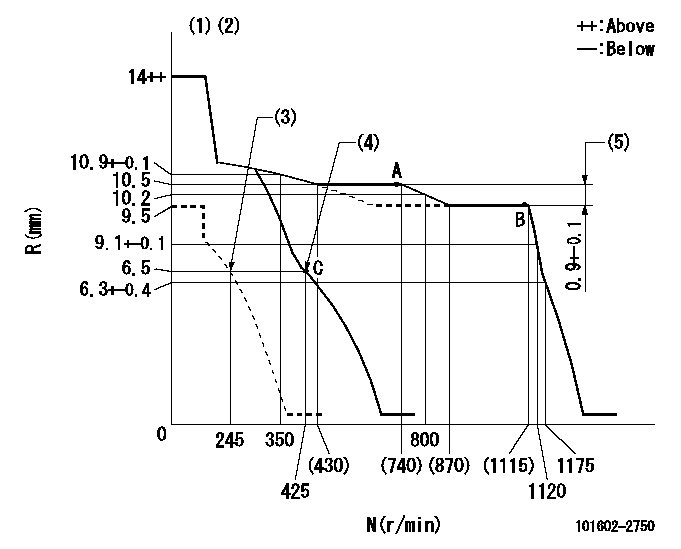
N:Pump speed
R:Rack position (mm)
(1)Target notch: K
(2)Tolerance for racks not indicated: +-0.05mm.
(3)Set idle sub-spring
(4)Main spring setting
(5)Rack difference between N = N1 and N = N2
----------
K=10 N1=1100r/min N2=700r/min
----------
----------
K=10 N1=1100r/min N2=700r/min
----------
Speed control lever angle
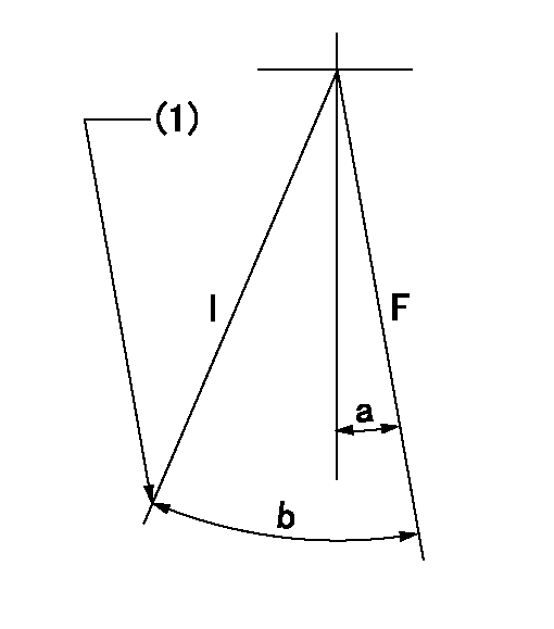
F:Full speed
I:Idle
(1)Stopper bolt setting
----------
----------
a=8deg+-5deg b=23deg+-5deg
----------
----------
a=8deg+-5deg b=23deg+-5deg
Stop lever angle

N:Pump normal
S:Stop the pump.
(1)Pump speed aa and rack position bb (to be sealed at delivery)
----------
aa=0r/min bb=1-0.2mm
----------
a=21deg+-5deg b=55deg+-5deg
----------
aa=0r/min bb=1-0.2mm
----------
a=21deg+-5deg b=55deg+-5deg
Timing setting

(1)Pump vertical direction
(2)Position of gear's standard threaded hole at No 1 cylinder's beginning of injection
(3)-
(4)-
----------
----------
a=(70deg)
----------
----------
a=(70deg)
Information:
Introduction
The problem identified below does not have a permanent solution. Until a permanent solution is known, use the solution that is identified below.Problem
There have been some instances of faults with the 459-7216 DEF Injector & Mounting Gp. The faults can lead to the Diesel Exhaust Fluid (DEF) injector not dosing correctly. Diagnostic trouble codes and operator inducements may become active due to these faults.Solution
Follow the correct troubleshooting procedure for any diagnostic codes related to the DEF system. Refer to Troubleshooting for the correct procedure. Diagnostic code 3361–5 Aftertreatment #1 DEF Dosing Unit : Current Below Normal has been reported, which may lead to operator inducement diagnostic codes 5246-15 Aftertreatment SCR Operator Inducement : Severity : High - least severe (1) and 5246-16 Aftertreatment SCR Operator Inducement : Severity : High - moderate severity.If the troubleshooting procedure indicates a DEF injector fault, perform the following procedure:
Ensure that the latest engine software is installed on the engine ECM. Refer to Troubleshooting, ECM Software - Install for the correct procedure.
Illustration 1 g06123677
View of the 459-7216 DEF Injector & Mounting Gp
(1) DEF injector part number
(2) Cavity number
Record the DEF injector part number (1), serial number, and cavity number (2).Note: The cavity number will be either a "1", a "2", or a "3".
If the DEF injector serial number is between "SN150702094314" and "SN160722000000" and the cavity number is "1", continue with this procedure.If the DEF injector serial number is outside of the range specified above, proceed to Test Step 4.If the cavity number is "2" or a "3", proceed to Test Step 4.
Install a replacement DEF injector. Refer to