Information injection-pump assembly
ZEXEL
101602-2710
1016022710
HINO
220204220A
220204220a

Rating:
Cross reference number
ZEXEL
101602-2710
1016022710
HINO
220204220A
220204220a
Zexel num
Bosch num
Firm num
Name
Calibration Data:
Adjustment conditions
Test oil
1404 Test oil ISO4113 or {SAEJ967d}
1404 Test oil ISO4113 or {SAEJ967d}
Test oil temperature
degC
40
40
45
Nozzle and nozzle holder
105780-8140
Bosch type code
EF8511/9A
Nozzle
105780-0000
Bosch type code
DN12SD12T
Nozzle holder
105780-2080
Bosch type code
EF8511/9
Opening pressure
MPa
17.2
Opening pressure
kgf/cm2
175
Injection pipe
Outer diameter - inner diameter - length (mm) mm 6-2-600
Outer diameter - inner diameter - length (mm) mm 6-2-600
Overflow valve
134424-0920
Overflow valve opening pressure
kPa
162
147
177
Overflow valve opening pressure
kgf/cm2
1.65
1.5
1.8
Tester oil delivery pressure
kPa
157
157
157
Tester oil delivery pressure
kgf/cm2
1.6
1.6
1.6
Direction of rotation (viewed from drive side)
Right R
Right R
Injection timing adjustment
Direction of rotation (viewed from drive side)
Right R
Right R
Injection order
1-4-2-6-
3-5
Pre-stroke
mm
3.8
3.77
3.83
Beginning of injection position
Drive side NO.1
Drive side NO.1
Difference between angles 1
Cal 1-4 deg. 60 59.75 60.25
Cal 1-4 deg. 60 59.75 60.25
Difference between angles 2
Cyl.1-2 deg. 120 119.75 120.25
Cyl.1-2 deg. 120 119.75 120.25
Difference between angles 3
Cal 1-6 deg. 180 179.75 180.25
Cal 1-6 deg. 180 179.75 180.25
Difference between angles 4
Cal 1-3 deg. 240 239.75 240.25
Cal 1-3 deg. 240 239.75 240.25
Difference between angles 5
Cal 1-5 deg. 300 299.75 300.25
Cal 1-5 deg. 300 299.75 300.25
Injection quantity adjustment
Adjusting point
A
Rack position
10.7
Pump speed
r/min
800
800
800
Average injection quantity
mm3/st.
85.5
83.5
87.5
Max. variation between cylinders
%
0
-3.5
3.5
Basic
*
Fixing the lever
*
Injection quantity adjustment_02
Adjusting point
C
Rack position
8.2+-0.5
Pump speed
r/min
375
375
375
Average injection quantity
mm3/st.
13
12
14
Max. variation between cylinders
%
0
-10
10
Fixing the rack
*
Injection quantity adjustment_03
Adjusting point
D
Rack position
-
Pump speed
r/min
100
100
100
Average injection quantity
mm3/st.
100
100
110
Fixing the lever
*
Rack limit
*
Test data Ex:
Governor adjustment
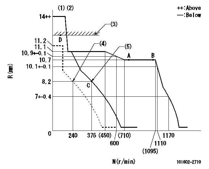
N:Pump speed
R:Rack position (mm)
(1)Target notch: K
(2)Tolerance for racks not indicated: +-0.05mm.
(3)RACK LIMIT
(4)Set idle sub-spring
(5)Main spring setting
----------
K=15
----------
----------
K=15
----------
Speed control lever angle

F:Full speed
I:Idle
(1)Stopper bolt setting
----------
----------
a=13deg+-5deg b=27deg+-5deg
----------
----------
a=13deg+-5deg b=27deg+-5deg
Stop lever angle

N:Pump normal
S:Stop the pump.
(1)Rack position aa or less, pump speed bb
----------
aa=7.7mm bb=0r/min
----------
a=27deg+-5deg b=53deg+-5deg
----------
aa=7.7mm bb=0r/min
----------
a=27deg+-5deg b=53deg+-5deg
Timing setting

(1)Pump vertical direction
(2)Coupling's key groove position at No 1 cylinder's beginning of injection
(3)-
(4)-
----------
----------
a=(50deg)
----------
----------
a=(50deg)
Information:
Introduction
This Special Instruction addresses the issue about the amount of ash in the DPF, and whether the DPF must be cleaned. Use the following procedure in order to determine if the DPF must be cleaned.Procedure
Note: This test is not designed to determine if a DPF is clean, only to determine if the DPF must be cleaned.
Perform a crack detection test. Refer to Special Instruction, REHS5017. Go to Step 2 if the DPF passes the crack detection test. Contact the Technical Communicator, if the DPF fails the test
Use a wire with the maximum diameter of 1.04140 mm (0.041 inch). Hold the wire so that the end of the wire is just inside the cell approximately 6.35000 mm (0.25 inch).
Drop the wire into the cell of the DPF.
Mark the wire at the top of the cell where the wire exits from the DPF.
Measure the depth that the wire dropped by measuring from the mark to the bottom tip of the wire.
Record the measurement.
Illustration 1 g03021156
Top view of DPFView of locations for recording measurements (1) Weld line
Perform Steps 3 through 6 for all locations. Refer to Illustration 1 for the proper location for recording measurements.
Average the measurements and subtract the average from the length of the DPF substrate length. The DPF must be cleaned if the number is more than 6 inches. Replace the DPF if the DPF cannot be cleaned.