Information injection-pump assembly
BOSCH
9 400 614 791
9400614791
ZEXEL
101602-2700
1016022700
HINO
220203990A
220203990a
Rating:
Service parts 101602-2700 INJECTION-PUMP ASSEMBLY:
1.
_
5.
AUTOM. ADVANCE MECHANIS
6.
COUPLING PLATE
8.
_
9.
_
11.
Nozzle and Holder
23600-1710
12.
Open Pre:MPa(Kqf/cm2)
21.6{220}
15.
NOZZLE SET
Cross reference number
BOSCH
9 400 614 791
9400614791
ZEXEL
101602-2700
1016022700
HINO
220203990A
220203990a
Zexel num
Bosch num
Firm num
Name
101602-2700
9 400 614 791
220203990A HINO
INJECTION-PUMP ASSEMBLY
W06D-T K
W06D-T K
Calibration Data:
Adjustment conditions
Test oil
1404 Test oil ISO4113 or {SAEJ967d}
1404 Test oil ISO4113 or {SAEJ967d}
Test oil temperature
degC
40
40
45
Nozzle and nozzle holder
105780-8140
Bosch type code
EF8511/9A
Nozzle
105780-0000
Bosch type code
DN12SD12T
Nozzle holder
105780-2080
Bosch type code
EF8511/9
Opening pressure
MPa
17.2
Opening pressure
kgf/cm2
175
Injection pipe
Outer diameter - inner diameter - length (mm) mm 6-2-600
Outer diameter - inner diameter - length (mm) mm 6-2-600
Overflow valve
131424-5720
Overflow valve opening pressure
kPa
255
221
289
Overflow valve opening pressure
kgf/cm2
2.6
2.25
2.95
Tester oil delivery pressure
kPa
157
157
157
Tester oil delivery pressure
kgf/cm2
1.6
1.6
1.6
Direction of rotation (viewed from drive side)
Right R
Right R
Injection timing adjustment
Direction of rotation (viewed from drive side)
Right R
Right R
Injection order
1-4-2-6-
3-5
Pre-stroke
mm
3.3
3.25
3.35
Beginning of injection position
Drive side NO.1
Drive side NO.1
Difference between angles 1
Cal 1-4 deg. 60 59.5 60.5
Cal 1-4 deg. 60 59.5 60.5
Difference between angles 2
Cyl.1-2 deg. 120 119.5 120.5
Cyl.1-2 deg. 120 119.5 120.5
Difference between angles 3
Cal 1-6 deg. 180 179.5 180.5
Cal 1-6 deg. 180 179.5 180.5
Difference between angles 4
Cal 1-3 deg. 240 239.5 240.5
Cal 1-3 deg. 240 239.5 240.5
Difference between angles 5
Cal 1-5 deg. 300 299.5 300.5
Cal 1-5 deg. 300 299.5 300.5
Injection quantity adjustment
Adjusting point
A
Rack position
9.1
Pump speed
r/min
900
900
900
Average injection quantity
mm3/st.
65.3
62.3
68.3
Max. variation between cylinders
%
0
-3
3
Basic
*
Fixing the lever
*
Injection quantity adjustment_02
Adjusting point
B
Rack position
6.1+-0.5
Pump speed
r/min
315
315
315
Average injection quantity
mm3/st.
9.6
8.1
11.1
Max. variation between cylinders
%
0
-15
15
Fixing the rack
*
Injection quantity adjustment_03
Adjusting point
C
Rack position
-
Pump speed
r/min
100
100
100
Average injection quantity
mm3/st.
106
106
116
Fixing the lever
*
Rack limit
*
Test data Ex:
Governor adjustment
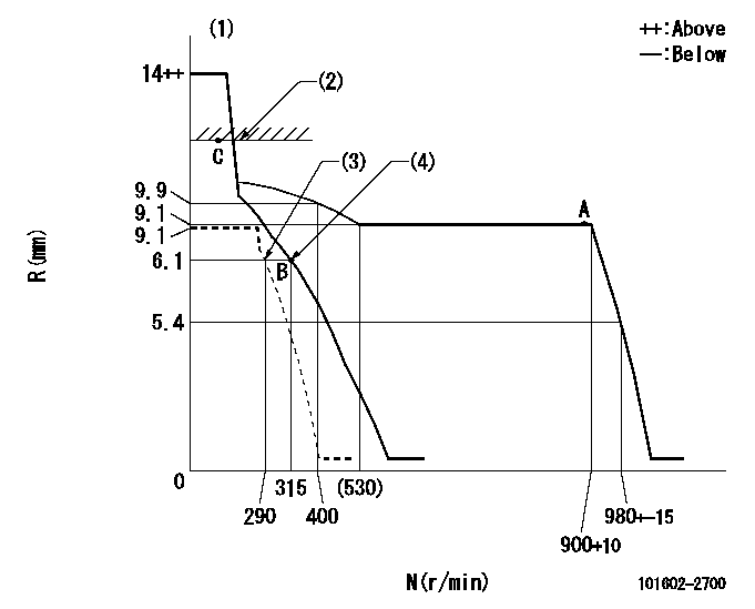
N:Pump speed
R:Rack position (mm)
(1)Target notch: K
(2)RACK LIMIT
(3)Set idle sub-spring
(4)Main spring setting
----------
K=8
----------
----------
K=8
----------
Speed control lever angle
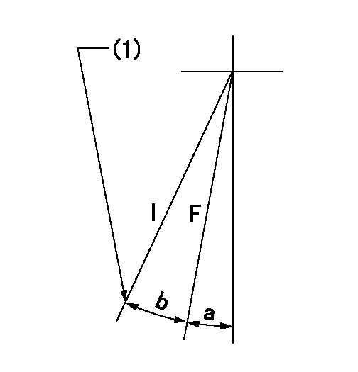
F:Full speed
I:Idle
(1)Stopper bolt setting
----------
----------
a=5deg+-5deg b=20deg+-5deg
----------
----------
a=5deg+-5deg b=20deg+-5deg
Stop lever angle

N:Pump normal
S:Stop the pump.
(1)Rack position aa or less, pump speed bb
----------
aa=5.6mm bb=0r/min
----------
a=27deg+-5deg b=53deg+-5deg
----------
aa=5.6mm bb=0r/min
----------
a=27deg+-5deg b=53deg+-5deg
Timing setting

(1)Pump vertical direction
(2)Position of gear's standard threaded hole at No 1 cylinder's beginning of injection
(3)-
(4)-
----------
----------
a=(70deg)
----------
----------
a=(70deg)
Information:
Do not operate or work on this machine unless you have read and understand the instructions and warnings in the Operation and Maintenance Manual. Failure to follow the instructions or heed the warnings could result in injury or death. Contact your Caterpillar dealer for replacement manuals. Proper care is your responsibility.
Personal injury or death can result from improper assembly procedures.Do not attempt any assembly until you have read and understand the assembly instructions.
Accidental engine starting can cause injury or death to personnel working on the equipment.To avoid accidental engine starting, disconnect the battery cable from the negative (−) battery terminal. Completely tape all metal surfaces of the disconnected battery cable end in order to prevent contact with other metal surfaces which could activate the engine electrical system.Place a Do Not Operate tag at the Start/Stop switch location to inform personnel that the equipment is being worked on.
Required Parts
Table 1
Required Tools
Tool Part Number Part Name Qty
A 9S-9150 Terminal Crimp Tool As 1
B 9U-6070 Heat Gun Gp 1 Removal of a Connector from the Wire Harness
The following steps can be used to remove a connector for an injector on the wire harness.
Identify the connectors that need to be replaced. Wiring for the injector solenoid is not sensitive to polarity.
Illustration 1 g06093848
Connectors that are cut from the wire harness
Each injector will have two connectors. The wire on one connector will be longer than the other. Wire (A) is identified as the longer wire and wire (B) is identified as the shorter wire.
Cut wire (2) at a distance of 50 mm (1.9 inch) from the rear surface of the connector.
Cut wire (1) at a distance of 5 mm (0.2 inch) from the cut made on wire (2).
Illustration 2 g01111314
Wire from the harness for side (B) on the connector.
Wire from the harness for side (A) on the connector.Note: The wires on the old connector are cut to length so that the wires on the wire harness will match up to the new connector. Cutting the wires to the proper length will aid in matching the harness wires to the wires on the new connector.
Discard the old connectors.Installation of a New Connector
The following steps can be used to install a new connector for an injector on the wire harness that is located under the valve mechanism cover.
Use Tool (A) to remove 5 mm (0.2 inch) of the plastic from wires (3) and (4).
Illustration 3 g06125254
Connecting the connector to the wire harness
(A) Side (A) of the new connector
(B) Side (B) of the new connector
(3) Wire from the harness for side (B) on the new connector
(4) Wire from the harness for side (A) on the new connector
(5) Heat shrink tubes
(6) Butt splice on the wire that is on side (A) of the new connector
(7) Butt splice on the wire that is on side (B) of the new connector
Use heat shrink tubes (5) from the 257-4183 Injector Wiring Harness Kit. Slide the heat shrink tubes toward the connector to expose the butt splices.
Insert wire (4) into
Have questions with 101602-2700?
Group cross 101602-2700 ZEXEL
Hino
101602-2700
9 400 614 791
220203990A
INJECTION-PUMP ASSEMBLY
W06D-T
W06D-T