Information injection-pump assembly
BOSCH
9 400 614 790
9400614790
ZEXEL
101602-2691
1016022691
HINO
220203940A
220203940a
Rating:
Service parts 101602-2691 INJECTION-PUMP ASSEMBLY:
1.
_
5.
AUTOM. ADVANCE MECHANIS
7.
COUPLING PLATE
8.
_
9.
_
11.
Nozzle and Holder
23600-2133
12.
Open Pre:MPa(Kqf/cm2)
19.6{200}
15.
NOZZLE SET
Cross reference number
BOSCH
9 400 614 790
9400614790
ZEXEL
101602-2691
1016022691
HINO
220203940A
220203940a
Zexel num
Bosch num
Firm num
Name
101602-2691
9 400 614 790
220203940A HINO
INJECTION-PUMP ASSEMBLY
H07D K 14BF INJECTION PUMP ASSY PE6AD PE
H07D K 14BF INJECTION PUMP ASSY PE6AD PE
Calibration Data:
Adjustment conditions
Test oil
1404 Test oil ISO4113 or {SAEJ967d}
1404 Test oil ISO4113 or {SAEJ967d}
Test oil temperature
degC
40
40
45
Nozzle and nozzle holder
105780-8140
Bosch type code
EF8511/9A
Nozzle
105780-0000
Bosch type code
DN12SD12T
Nozzle holder
105780-2080
Bosch type code
EF8511/9
Opening pressure
MPa
17.2
Opening pressure
kgf/cm2
175
Injection pipe
Outer diameter - inner diameter - length (mm) mm 6-2-600
Outer diameter - inner diameter - length (mm) mm 6-2-600
Overflow valve
134424-0920
Overflow valve opening pressure
kPa
162
147
177
Overflow valve opening pressure
kgf/cm2
1.65
1.5
1.8
Tester oil delivery pressure
kPa
157
157
157
Tester oil delivery pressure
kgf/cm2
1.6
1.6
1.6
Direction of rotation (viewed from drive side)
Right R
Right R
Injection timing adjustment
Direction of rotation (viewed from drive side)
Right R
Right R
Injection order
1-4-2-6-
3-5
Pre-stroke
mm
3.8
3.77
3.83
Beginning of injection position
Drive side NO.1
Drive side NO.1
Difference between angles 1
Cal 1-4 deg. 60 59.75 60.25
Cal 1-4 deg. 60 59.75 60.25
Difference between angles 2
Cyl.1-2 deg. 120 119.75 120.25
Cyl.1-2 deg. 120 119.75 120.25
Difference between angles 3
Cal 1-6 deg. 180 179.75 180.25
Cal 1-6 deg. 180 179.75 180.25
Difference between angles 4
Cal 1-3 deg. 240 239.75 240.25
Cal 1-3 deg. 240 239.75 240.25
Difference between angles 5
Cal 1-5 deg. 300 299.75 300.25
Cal 1-5 deg. 300 299.75 300.25
Injection quantity adjustment
Adjusting point
A
Rack position
10
Pump speed
r/min
900
900
900
Average injection quantity
mm3/st.
96.6
95.6
97.6
Max. variation between cylinders
%
0
-3.5
3.5
Basic
*
Fixing the lever
*
Injection quantity adjustment_02
Adjusting point
C
Rack position
7.5+-0.5
Pump speed
r/min
435
435
435
Average injection quantity
mm3/st.
8
7
9
Max. variation between cylinders
%
0
-10
10
Fixing the rack
*
Injection quantity adjustment_03
Adjusting point
D
Rack position
-
Pump speed
r/min
100
100
100
Average injection quantity
mm3/st.
124
124
134
Fixing the lever
*
Rack limit
*
Test data Ex:
Governor adjustment
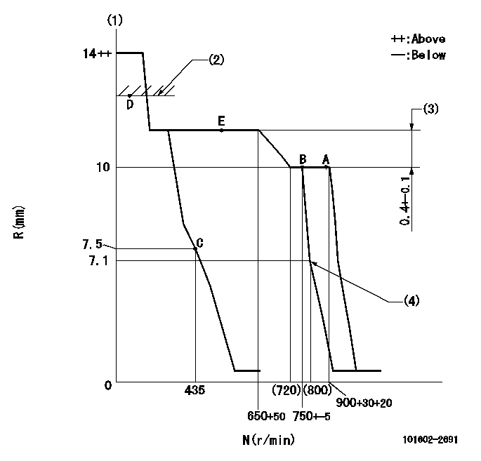
N:Pump speed
R:Rack position (mm)
(1)Notch fixed: K
(2)RACK LIMIT
(3)Rack difference between N = N1 and N = N2
(4)Idle sub spring setting: L1.
----------
K=12 N1=900r/min N2=500r/min L1=7.2-0.2mm
----------
----------
K=12 N1=900r/min N2=500r/min L1=7.2-0.2mm
----------
Speed control lever angle
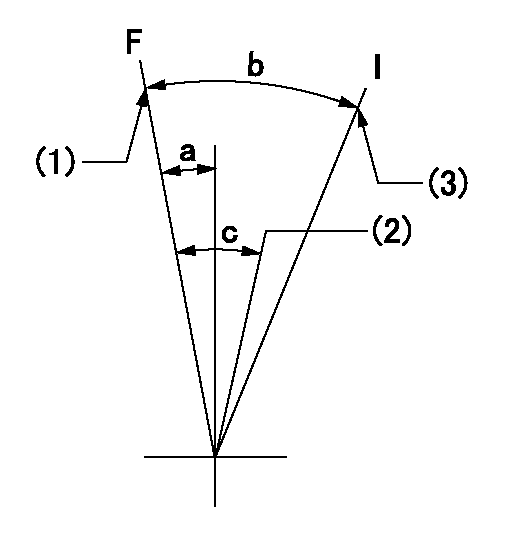
F:Full speed
I:Idle
(1)Set the speed at aa (set the stopper bolt).
(2)Set the pump speed at bb.
(3)Stopper bolt setting
----------
aa=900r/min bb=750r/min
----------
a=(5deg)+-5deg b=(17deg)+-5deg c=(6deg)+-5deg
----------
aa=900r/min bb=750r/min
----------
a=(5deg)+-5deg b=(17deg)+-5deg c=(6deg)+-5deg
Stop lever angle
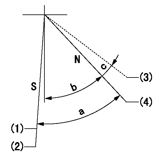
N:Pump normal
S:Stop the pump.
(1)At delivery
(2)Rack position aa or less, pump speed bb
(3)Contacts normal side pin
(4)Clearance from the pin on the normal side: cc
----------
aa=7mm bb=0r/min cc=2.5+-0.5mm
----------
a=53deg+-5deg b=51deg+-5deg c=(6deg)
----------
aa=7mm bb=0r/min cc=2.5+-0.5mm
----------
a=53deg+-5deg b=51deg+-5deg c=(6deg)
Timing setting

(1)Pump vertical direction
(2)Coupling's key groove position at No 1 cylinder's beginning of injection
(3)-
(4)-
----------
----------
a=(50deg)
----------
----------
a=(50deg)
Information:
Indicator Readings
If, the indicator reading a positive (+), the tip of the indicator moved into the indicator and minus (-) means that the tip of the indicator moved out of the dial indicator.When comparing two positive (+) indicator readings, the larger numerical reading is more than the smaller numerical reading. However, when comparing two minus (-) indicator readings, the larger numerical reading is less than the smaller numerical reading. In both cases, the indicator reading becomes less as the tip of the indicator moves out of the dial indicator.The Total Indicator Reading (TIR) is the total amount of movement of the indicator needle. The TIR is always a positive value even though one or both of the readings are negative. For example: If the indicator reading varied from -10 to +5, the TIR was 15. If the indicator reading is varied from -5 to - 15, the TIR was 10.Laser Tool Alignment Procedure
Note: Refer to the laser alignment tool user manual instructions for additional information regarding operation of the tool.To do laser tool alignment, perform the following steps:
Mount the transducer to the outer coupling element.
Attach the reflector to the generator hub.
Enter the required dimensions into the laser alignment tool. Examples of possible dimensions required include the following:
Transducer to reflector
Transducer to coupling centerline
Coupling diameter
Rotations Per Minute (RPM)
Transducer to front feet
Front feet to rear feet
Turn the laser ON, adjust the laser beam to the center of the reflector dust cap. Once the laser beam is centered, remove the dust cap.
Rotate the drive line one complete revolution.
Record the results displayed on the laser alignment tool. Compare the readings to the acceptable values listed in the "Generator Set Alignment Data Sheet".
Adjust the generator as needed to obtain the correct alignment. Shims may be installed or removed to achieve the correct vertical alignment. Use the horizontal adjustment screws to make horizontal adjustments.
Once the alignment is within the specifications, torque the generator mounting bolts to the proper specifications.
Perform a soft foot check. Refer to "Soft Foot Check Procedure".Soft Foot Check Procedure
Note: The soft foot check can be completed with the laser alignment tool if the tool has this function.
Ensure that all jacking screws are loose
Mount a dial indicator from the base assembly to the top of the generator mounting foot to be measured.
Preload the dial indicator to a minimum of one revolution or 2 mm (0.08 inch). Once the correct preload is set, zero the dial indicator.
Loosen the mounting bolt at the location that is being measured. Measure and record the vertical deflection of the generator mounting foot at this location as close to the mounting bolt as possible. Only loosen one bolt at a time.
The maximum deflection of the mounting foot is 0.076 mm (0.003 inch). If the indicator reading is greater than this amount, add shims to eliminate the soft foot condition. Torque the mounting bolt before moving to the next mounting foot to be measured for soft foot.
Repeat the procedure on the remaining generator mounting feet.
Perform the final torque of the
Have questions with 101602-2691?
Group cross 101602-2691 ZEXEL
Hino
Hino
Hino
Hino
101602-2691
9 400 614 790
220203940A
INJECTION-PUMP ASSEMBLY
H07D
H07D
