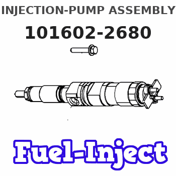
Information injection-pump assembly
ZEXEL
101602-2680
1016022680
Rating:
Service parts 101602-2680 INJECTION-PUMP ASSEMBLY:
1.
_
5.
AUTOM. ADVANCE MECHANIS
6.
COUPLING PLATE
8.
_
9.
_
11.
Nozzle and Holder
23600-1710A
12.
Open Pre:MPa(Kqf/cm2)
21.6{220}
15.
NOZZLE SET
Cross reference number
ZEXEL
101602-2680
1016022680
Zexel num
Bosch num
Firm num
Name
101602-2680
INJECTION-PUMP ASSEMBLY
14BE PE6A PE
14BE PE6A PE
Calibration Data:
Adjustment conditions
Test oil
1404 Test oil ISO4113 or {SAEJ967d}
1404 Test oil ISO4113 or {SAEJ967d}
Test oil temperature
degC
40
40
45
Nozzle and nozzle holder
105780-8140
Bosch type code
EF8511/9A
Nozzle
105780-0000
Bosch type code
DN12SD12T
Nozzle holder
105780-2080
Bosch type code
EF8511/9
Opening pressure
MPa
17.2
Opening pressure
kgf/cm2
175
Injection pipe
Outer diameter - inner diameter - length (mm) mm 6-2-600
Outer diameter - inner diameter - length (mm) mm 6-2-600
Overflow valve
131424-5720
Overflow valve opening pressure
kPa
255
221
289
Overflow valve opening pressure
kgf/cm2
2.6
2.25
2.95
Tester oil delivery pressure
kPa
157
157
157
Tester oil delivery pressure
kgf/cm2
1.6
1.6
1.6
Direction of rotation (viewed from drive side)
Right R
Right R
Injection timing adjustment
Direction of rotation (viewed from drive side)
Right R
Right R
Injection order
1-4-2-6-
3-5
Pre-stroke
mm
3.4
3.35
3.45
Beginning of injection position
Drive side NO.1
Drive side NO.1
Difference between angles 1
Cal 1-4 deg. 60 59.5 60.5
Cal 1-4 deg. 60 59.5 60.5
Difference between angles 2
Cyl.1-2 deg. 120 119.5 120.5
Cyl.1-2 deg. 120 119.5 120.5
Difference between angles 3
Cal 1-6 deg. 180 179.5 180.5
Cal 1-6 deg. 180 179.5 180.5
Difference between angles 4
Cal 1-3 deg. 240 239.5 240.5
Cal 1-3 deg. 240 239.5 240.5
Difference between angles 5
Cal 1-5 deg. 300 299.5 300.5
Cal 1-5 deg. 300 299.5 300.5
Injection quantity adjustment
Adjusting point
A
Rack position
10.4
Pump speed
r/min
1400
1400
1400
Average injection quantity
mm3/st.
86
84
88
Max. variation between cylinders
%
0
-3
3
Basic
*
Fixing the lever
*
Boost pressure
kPa
26.7
26.7
Boost pressure
mmHg
200
200
Injection quantity adjustment_02
Adjusting point
B
Rack position
7.3+-0.5
Pump speed
r/min
360
360
360
Average injection quantity
mm3/st.
9
7.5
10.5
Max. variation between cylinders
%
0
-15
15
Fixing the rack
*
Boost pressure
kPa
0
0
0
Boost pressure
mmHg
0
0
0
Injection quantity adjustment_03
Adjusting point
E
Rack position
-
Pump speed
r/min
100
100
100
Average injection quantity
mm3/st.
98
98
108
Fixing the lever
*
Boost pressure
kPa
0
0
0
Boost pressure
mmHg
0
0
0
Rack limit
*
Boost compensator adjustment
Pump speed
r/min
600
600
600
Rack position
R1-1.2
Boost pressure
kPa
2
2
4.7
Boost pressure
mmHg
15
15
35
Boost compensator adjustment_02
Pump speed
r/min
600
600
600
Rack position
R1(10.4)
Boost pressure
kPa
13.3
13.3
13.3
Boost pressure
mmHg
100
100
100
Test data Ex:
Governor adjustment
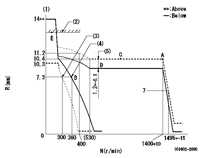
N:Pump speed
R:Rack position (mm)
(1)Target notch: K
(2)RACK LIMIT
(3)Set idle sub-spring
(4)Main spring setting
(5)Boost compensator stroke
----------
K=12
----------
----------
K=12
----------
Speed control lever angle
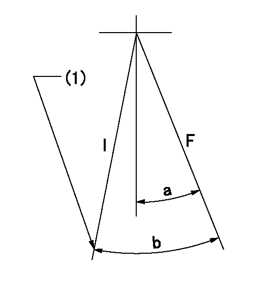
F:Full speed
I:Idle
(1)Stopper bolt setting
----------
----------
a=15deg+-5deg b=28deg+-5deg
----------
----------
a=15deg+-5deg b=28deg+-5deg
Stop lever angle

N:Pump normal
S:Stop the pump.
(1)Pump speed aa and rack position bb (to be sealed at delivery)
----------
aa=0r/min bb=1-0.2mm
----------
a=21deg+-5deg b=(55deg)
----------
aa=0r/min bb=1-0.2mm
----------
a=21deg+-5deg b=(55deg)
Timing setting

(1)Pump vertical direction
(2)Position of gear's standard threaded hole at No 1 cylinder's beginning of injection
(3)-
(4)-
----------
----------
a=(70deg)
----------
----------
a=(70deg)
Information:
Illustration 62 g02807941
Remove the plug
Remove plug (2) .
Illustration 63 g02807956
Set speed by turning adjusting screw
Adjust speed. If Ng exceeds TMI specifications, tighten the adjusting screw. If Ng is less than the specified value, loosen the adjusting screw.
Illustration 64 g02807957
Adjust the maximum-speed stopper bolt
Adjust the maximum-speed stopper bolt until the speed at the start of high-speed control is Nf.
Check that the no-load maximum speed is Ng (described in Step 1). Continue adjustment until the specified value is obtained.
Illustration 65 g02807958
Increase pump speed to make sure that the control rack position reaches Ra.
Illustration 66 g02807959
Full-load Adjustment
Illustration 67 g02807997
Install the cover and adjust full-load stopper bolt
Install cover (3) on governor using bolts and lockwashers (2). Use caution when installing the cover to make sure that the O-ring seal is in the seal groove.
Illustration 68 g02807999
Position the control lever at maximum-speed position.
Adjust full-load stopper bolt (1) to the f"ull-load fuel injection quantity" position. See TMI for the specifications (Point A).
Install cap.Control Lever Angle Measurement
Illustration 69 g02808016
Measuring control lever angle at the "full-speed" and "idling" positions.
Measuring the control lever angle at the "idling" and "full" positions.
If the angle is not as specified by TMI, replace the shifters shim. If the control lever is positioned toward the "full" position, replace the shifters shim with a thicker one. When control lever is toward the "idling" position, replace the shim with a thinner one.Check Starting Delivery
Illustration 70 g02808018
Remove measurement adapter
Remove measurement adapter (1) .
Illustration 71 g02808038
Cap must be installed to check delivery rate
Install cap (2) .
Run pump at speed specified in TMI.
Check delivery rate with specifications listed in TMI.
Stop pump rotation.
Illustration 72 g02808058
Adjusting screw for setting fuel flow
If delivery rate does not meet TMI specifications, remove cap (2), loosen lock nut, and adjust screw (3). Adjusting screw outward decreases fuel flow and inward increases fuel flow.
Install cap (2) and recheck delivery rate. Repeat Steps 2 through 6 until delivery rate is at specified value.Lockwiring Caps of Adjustment Screws
All adjustment stops (screws) that directly affect engine performance should be lockwired after adjustment. Do not readjust any stop without using the test stand can adversely affect the engine and engine performance.
Have questions with 101602-2680?
Group cross 101602-2680 ZEXEL
Hino
Hino
101602-2680
INJECTION-PUMP ASSEMBLY