Information injection-pump assembly
BOSCH
9 400 614 786
9400614786
ZEXEL
101602-2650
1016022650
HINO
220203890A
220203890a
Rating:
Service parts 101602-2650 INJECTION-PUMP ASSEMBLY:
1.
_
5.
AUTOM. ADVANCE MECHANIS
6.
COUPLING PLATE
8.
_
9.
_
11.
Nozzle and Holder
23600-1710
12.
Open Pre:MPa(Kqf/cm2)
21.6{220}
15.
NOZZLE SET
Cross reference number
BOSCH
9 400 614 786
9400614786
ZEXEL
101602-2650
1016022650
HINO
220203890A
220203890a
Zexel num
Bosch num
Firm num
Name
101602-2650
9 400 614 786
220203890A HINO
INJECTION-PUMP ASSEMBLY
W06D-T K
W06D-T K
Calibration Data:
Adjustment conditions
Test oil
1404 Test oil ISO4113 or {SAEJ967d}
1404 Test oil ISO4113 or {SAEJ967d}
Test oil temperature
degC
40
40
45
Nozzle and nozzle holder
105780-8140
Bosch type code
EF8511/9A
Nozzle
105780-0000
Bosch type code
DN12SD12T
Nozzle holder
105780-2080
Bosch type code
EF8511/9
Opening pressure
MPa
17.2
Opening pressure
kgf/cm2
175
Injection pipe
Outer diameter - inner diameter - length (mm) mm 6-2-600
Outer diameter - inner diameter - length (mm) mm 6-2-600
Overflow valve
131424-5720
Overflow valve opening pressure
kPa
255
221
289
Overflow valve opening pressure
kgf/cm2
2.6
2.25
2.95
Tester oil delivery pressure
kPa
157
157
157
Tester oil delivery pressure
kgf/cm2
1.6
1.6
1.6
Direction of rotation (viewed from drive side)
Right R
Right R
Injection timing adjustment
Direction of rotation (viewed from drive side)
Right R
Right R
Injection order
1-4-2-6-
3-5
Pre-stroke
mm
3.3
3.25
3.35
Beginning of injection position
Drive side NO.1
Drive side NO.1
Difference between angles 1
Cal 1-4 deg. 60 59.5 60.5
Cal 1-4 deg. 60 59.5 60.5
Difference between angles 2
Cyl.1-2 deg. 120 119.5 120.5
Cyl.1-2 deg. 120 119.5 120.5
Difference between angles 3
Cal 1-6 deg. 180 179.5 180.5
Cal 1-6 deg. 180 179.5 180.5
Difference between angles 4
Cal 1-3 deg. 240 239.5 240.5
Cal 1-3 deg. 240 239.5 240.5
Difference between angles 5
Cal 1-5 deg. 300 299.5 300.5
Cal 1-5 deg. 300 299.5 300.5
Injection quantity adjustment
Adjusting point
A
Rack position
9.1
Pump speed
r/min
1100
1100
1100
Average injection quantity
mm3/st.
72.2
69.2
75.2
Max. variation between cylinders
%
0
-3
3
Basic
*
Fixing the lever
*
Injection quantity adjustment_02
Adjusting point
B
Rack position
6.1+-0.5
Pump speed
r/min
315
315
315
Average injection quantity
mm3/st.
9.6
8.1
11.1
Max. variation between cylinders
%
0
-15
15
Fixing the rack
*
Injection quantity adjustment_03
Adjusting point
D
Rack position
-
Pump speed
r/min
100
100
100
Average injection quantity
mm3/st.
106
106
116
Fixing the lever
*
Rack limit
*
Test data Ex:
Governor adjustment
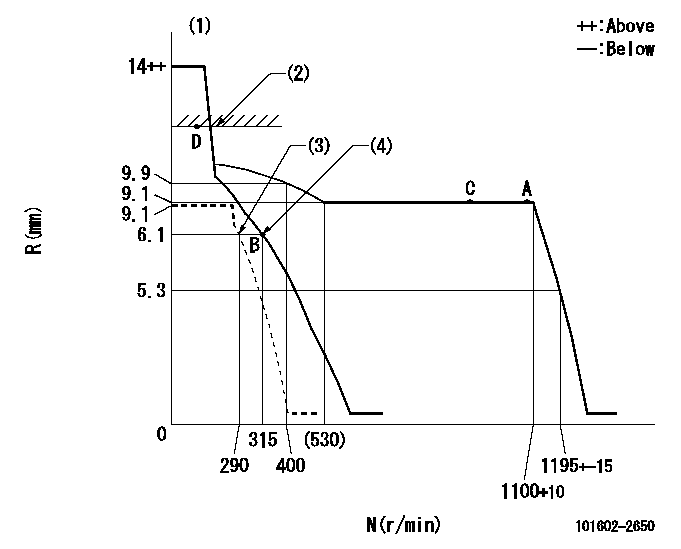
N:Pump speed
R:Rack position (mm)
(1)Target notch: K
(2)RACK LIMIT
(3)Set idle sub-spring
(4)Main spring setting
----------
K=10
----------
----------
K=10
----------
Speed control lever angle
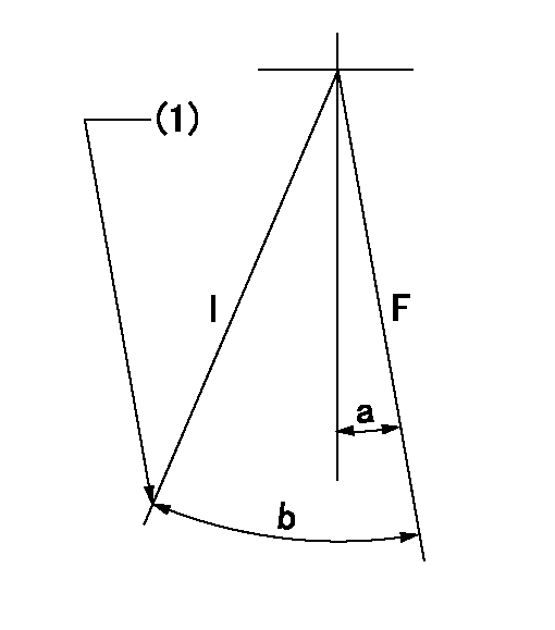
F:Full speed
I:Idle
(1)Stopper bolt setting
----------
----------
a=1deg+-5deg b=21deg+-5deg
----------
----------
a=1deg+-5deg b=21deg+-5deg
Stop lever angle

N:Pump normal
S:Stop the pump.
(1)Rack position aa or less, pump speed bb
----------
aa=5.6mm bb=0r/min
----------
a=27deg+-5deg b=53deg+-5deg
----------
aa=5.6mm bb=0r/min
----------
a=27deg+-5deg b=53deg+-5deg
Timing setting

(1)Pump vertical direction
(2)Position of gear's standard threaded hole at No 1 cylinder's beginning of injection
(3)-
(4)-
----------
----------
a=(70deg)
----------
----------
a=(70deg)
Information:
Repeat Steps 4 through 6 to remove (bleed) air from the rear table lift cylinder (not shown).
Open (CCW) hand pump control knob (11) to completely lower the DPF cleaner table. Close (CW) the hand pump control knob.
Illustration 38 g02728258
(28) Hydraulic Oil Level 51 to 102 mm (2.0 to 4.0 inch)
Check the oil level in the pump reservoir. Remove fill cap (13) located on the end cap of the hand pump. Hydraulic oil level (28) should be 51 to 102 mm (2.0 to 4.0 inch) from the bottom of the fill hole. Add high-grade hydraulic oil, if needed.Note: A clean wire tie can be used as a dipstick to measure the hydraulic oil level in the pump reservoir.Troubleshooting Guide
Table 3
Symptom Solution
Air dryer desiccant is a pinkish color. 1. Replace or regenerate the desiccant. Refer to ""Maintenance Section"".
Bursting does not occur. 1. Check display screen for error message.
2. Check power connection to burst valve solenoid.
Cabinet doors do not close correctly. 1. Look for damaged door hinges, seals, and latches.
2. Verify that vehicle sensors have been removed from DPF.
Cabinet doors open during burst process. 1. Verify that doors are correctly latched.
2. Look for damage to door latches.
3. Check seals between DPF and adapters.
Clamping force cannot be obtained. 1. Look for hydraulic fluid leaks.
2. Check fluid level in hydraulic pump. Refer to ""Maintenance Section"".
Clamping force does not hold. 1. Upon initial clamping, it is possible for clamp load to drop
689 to 1379 kPa (99.9 to 200.0 psi) within the first minute, due to temperature effects. After reclamping, the drop should be virtually zero.
2. Look for hydraulic fluid leaks.
Display screen is blank. 1. Verify that machine is ON, plugged into an outlet, and power is available to the outlet.
2. Reset circuit breakers located on left side of control cabinet.
DPF does not line up correctly on the table. 1. Verify that correct adapters are being used.
2. Verify DPF is correctly seated on to lower adapter.
DPF is damaged after cleaning process. 1. Check DPFs for damage before cleaning.
2. Look for damage on adapters.
3. Verify that correct cleaning protocol was entered into machine.
DPF is not cleaned. 1. Check orientation of DPF. Refer to ""General Information"" Section.
2. Verify that correct cleaning protocol was entered into machine.
3. Look for other DPF conditions that may prevent successful cleaning.
Have questions with 101602-2650?
Group cross 101602-2650 ZEXEL
Hino
Hino
101602-2650
9 400 614 786
220203890A
INJECTION-PUMP ASSEMBLY
W06D-T
W06D-T