Information injection-pump assembly
BOSCH
9 400 614 785
9400614785
ZEXEL
101602-2643
1016022643
HINO
220801563A
220801563a

Rating:
Include in #1:
101472-0061
as _
Cross reference number
BOSCH
9 400 614 785
9400614785
ZEXEL
101602-2643
1016022643
HINO
220801563A
220801563a
Zexel num
Bosch num
Firm num
Name
101602-2643
9 400 614 785
220801563A HINO
INJECTION-PUMP ASSEMBLY
W06D K
W06D K
Calibration Data:
Adjustment conditions
Test oil
1404 Test oil ISO4113 or {SAEJ967d}
1404 Test oil ISO4113 or {SAEJ967d}
Test oil temperature
degC
40
40
45
Nozzle and nozzle holder
105780-8140
Bosch type code
EF8511/9A
Nozzle
105780-0000
Bosch type code
DN12SD12T
Nozzle holder
105780-2080
Bosch type code
EF8511/9
Opening pressure
MPa
17.2
Opening pressure
kgf/cm2
175
Injection pipe
Outer diameter - inner diameter - length (mm) mm 6-2-600
Outer diameter - inner diameter - length (mm) mm 6-2-600
Overflow valve
134424-0920
Overflow valve opening pressure
kPa
162
147
177
Overflow valve opening pressure
kgf/cm2
1.65
1.5
1.8
Tester oil delivery pressure
kPa
157
157
157
Tester oil delivery pressure
kgf/cm2
1.6
1.6
1.6
RED3 control unit part number
407910-2
470
RED3 rack sensor specifications
mm
15
Direction of rotation (viewed from drive side)
Right R
Right R
Injection timing adjustment
Direction of rotation (viewed from drive side)
Right R
Right R
Injection order
1-4-2-6-
3-5
Pre-stroke
mm
3.1
3.05
3.15
Beginning of injection position
Drive side NO.1
Drive side NO.1
Difference between angles 1
Cal 1-4 deg. 60 59.5 60.5
Cal 1-4 deg. 60 59.5 60.5
Difference between angles 2
Cyl.1-2 deg. 120 119.5 120.5
Cyl.1-2 deg. 120 119.5 120.5
Difference between angles 3
Cal 1-6 deg. 180 179.5 180.5
Cal 1-6 deg. 180 179.5 180.5
Difference between angles 4
Cal 1-3 deg. 240 239.5 240.5
Cal 1-3 deg. 240 239.5 240.5
Difference between angles 5
Cal 1-5 deg. 300 299.5 300.5
Cal 1-5 deg. 300 299.5 300.5
Injection quantity adjustment
Rack position
(8.1)
Vist
V
2.38
2.38
2.38
Pump speed
r/min
900
900
900
Average injection quantity
mm3/st.
49.7
47.7
51.7
Max. variation between cylinders
%
0
-3
3
Basic
*
Injection quantity adjustment_02
Rack position
(5.8)
Vist
V
2.8
2.7
2.9
Pump speed
r/min
500
500
500
Average injection quantity
mm3/st.
9
7.5
10.5
Max. variation between cylinders
%
0
-15
15
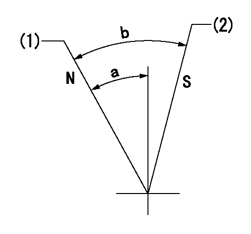
Test data Ex:
Speed control lever angle

N:Pump normal
S:Stop the pump.
(1)Rack position = aa
(2)Rack position bb
----------
aa=16mm bb=1mm
----------
a=19deg+-5deg b=29deg+-5deg
----------
aa=16mm bb=1mm
----------
a=19deg+-5deg b=29deg+-5deg
0000000901

(1)Pump vertical direction
(2)Position of gear's standard threaded hole at No 1 cylinder's beginning of injection
(3)-
(4)-
----------
----------
a=(70deg)
----------
----------
a=(70deg)
Stop lever angle

(Rs) rack sensor specifications
(C/U) control unit part number
(V) Rack sensor output voltage
(R) Rack position (mm)
1. Confirming governor output characteristics (rack 15 mm, span 6 mm)
(1)When the output voltages of the rack sensor are V1 and V2, check that the rack positions R1 and R2 in the table above are satisfied.
----------
----------
----------
----------
Information:
Installation Procedure
Table 1
Required Parts
Item Qty Part Number Description
1 1 285-1163 Cable
2 1 493-6051 Cover
3 1 5P-7958 Cable Splice Sleeve
Prepare the machine for maintenance. Refer to Operation and Maintenance Manual, "Prepare the Machine for Maintenance".
Illustration 1 g06048101
View of the Diesel Exhaust Fluid (DEF) tank
(A) Bolt
(1) 285-1163 Cable
Remove and retain bolt (A) that secures the cover to the fuel tank.
Secure cable (1) around bolt (A) and reinstall bolt (A).
Illustration 2 g06048083
View of the Diesel Exhaust Fluid (DEF) tank
(1) 285-1163 Cable
(2) 493-6051 Cover
(3) 5P-7958 Cable Splice Sleeve
Slide cover (2) over the fill tube on the tank.Insert the loose end of cable (1) through the hole of cover (2).Secure cable (1) with cable splice sleeve (3).
Have questions with 101602-2643?
Group cross 101602-2643 ZEXEL
Hino
Hino
101602-2643
9 400 614 785
220801563A
INJECTION-PUMP ASSEMBLY
W06D
W06D