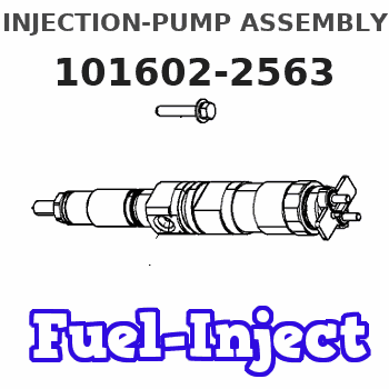
Information injection-pump assembly
BOSCH
9 400 614 783
9400614783
ZEXEL
101602-2563
1016022563
HINO
220203763A
220203763a

Rating:
Service parts 101602-2563 INJECTION-PUMP ASSEMBLY:
1.
_
5.
AUTOM. ADVANCE MECHANIS
7.
COUPLING PLATE
8.
_
9.
_
11.
Nozzle and Holder
23600-2133
12.
Open Pre:MPa(Kqf/cm2)
19.6{200}
15.
NOZZLE SET
Include in #1:
101602-2563
as INJECTION-PUMP ASSEMBLY
Include in #2:
104268-3041
as _
Cross reference number
BOSCH
9 400 614 783
9400614783
ZEXEL
101602-2563
1016022563
HINO
220203763A
220203763a
Zexel num
Bosch num
Firm num
Name
101602-2563
9 400 614 783
220203763A HINO
INJECTION-PUMP ASSEMBLY
H07D K 14BF INJECTION PUMP ASSY PE6AD PE
H07D K 14BF INJECTION PUMP ASSY PE6AD PE
101602-2563
9 400 614 783
S220203763A HINO
INJECTION-PUMP ASSEMBLY
H07D A K 14BF INJECTION PUMP ASSY PE6AD PE
H07D A K 14BF INJECTION PUMP ASSY PE6AD PE
Calibration Data:
Adjustment conditions
Test oil
1404 Test oil ISO4113 or {SAEJ967d}
1404 Test oil ISO4113 or {SAEJ967d}
Test oil temperature
degC
40
40
45
Nozzle and nozzle holder
105780-8140
Bosch type code
EF8511/9A
Nozzle
105780-0000
Bosch type code
DN12SD12T
Nozzle holder
105780-2080
Bosch type code
EF8511/9
Opening pressure
MPa
17.2
Opening pressure
kgf/cm2
175
Injection pipe
Outer diameter - inner diameter - length (mm) mm 6-2-600
Outer diameter - inner diameter - length (mm) mm 6-2-600
Overflow valve
134424-0920
Overflow valve opening pressure
kPa
162
147
177
Overflow valve opening pressure
kgf/cm2
1.65
1.5
1.8
Tester oil delivery pressure
kPa
157
157
157
Tester oil delivery pressure
kgf/cm2
1.6
1.6
1.6
Direction of rotation (viewed from drive side)
Right R
Right R
Injection timing adjustment
Direction of rotation (viewed from drive side)
Right R
Right R
Injection order
1-4-2-6-
3-5
Pre-stroke
mm
3.8
3.77
3.83
Beginning of injection position
Drive side NO.1
Drive side NO.1
Difference between angles 1
Cal 1-4 deg. 60 59.75 60.25
Cal 1-4 deg. 60 59.75 60.25
Difference between angles 2
Cyl.1-2 deg. 120 119.75 120.25
Cyl.1-2 deg. 120 119.75 120.25
Difference between angles 3
Cal 1-6 deg. 180 179.75 180.25
Cal 1-6 deg. 180 179.75 180.25
Difference between angles 4
Cal 1-3 deg. 240 239.75 240.25
Cal 1-3 deg. 240 239.75 240.25
Difference between angles 5
Cal 1-5 deg. 300 299.75 300.25
Cal 1-5 deg. 300 299.75 300.25
Injection quantity adjustment
Adjusting point
A
Rack position
10
Pump speed
r/min
900
900
900
Average injection quantity
mm3/st.
96.6
95.6
97.6
Max. variation between cylinders
%
0
-3.5
3.5
Basic
*
Fixing the lever
*
Injection quantity adjustment_02
Adjusting point
C
Rack position
7.5+-0.5
Pump speed
r/min
400
400
400
Average injection quantity
mm3/st.
8.5
7.5
9.5
Max. variation between cylinders
%
0
-10
10
Fixing the rack
*
Injection quantity adjustment_03
Adjusting point
D
Rack position
-
Pump speed
r/min
100
100
100
Average injection quantity
mm3/st.
124
124
134
Fixing the lever
*
Rack limit
*
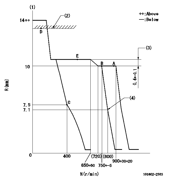
Test data Ex:
Governor adjustment

N:Pump speed
R:Rack position (mm)
(1)Notch fixed: K
(2)RACK LIMIT
(3)Rack difference between N = N1 and N = N2
(4)Idle sub spring setting: L1.
----------
K=12 N1=900r/min N2=500r/min L1=7.2-0.2mm
----------
----------
K=12 N1=900r/min N2=500r/min L1=7.2-0.2mm
----------
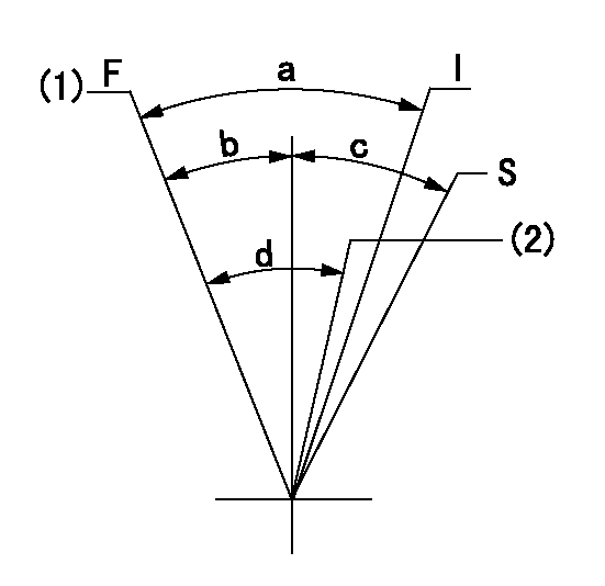
Speed control lever angle

F:Full speed
I:Idle
S:Stop
(1)Set the pump speed at aa. ( At delivery )
(2)Set the pump speed at bb.
----------
aa=900r/min bb=750r/min
----------
a=(19deg)+-5deg b=(4deg)+-5deg c=35deg+-3deg d=(6deg)+-5deg
----------
aa=900r/min bb=750r/min
----------
a=(19deg)+-5deg b=(4deg)+-5deg c=35deg+-3deg d=(6deg)+-5deg
Stop lever angle

N:Pump normal
S:Stop the pump.
(1)Rack position aa or less, pump speed bb
----------
aa=7mm bb=0r/min
----------
a=27deg+-5deg b=53deg+-5deg
----------
aa=7mm bb=0r/min
----------
a=27deg+-5deg b=53deg+-5deg
Timing setting

(1)Pump vertical direction
(2)Coupling's key groove position at No 1 cylinder's beginning of injection
(3)-
(4)-
----------
----------
a=(50deg)
----------
----------
a=(50deg)
Information:
Table 4
Storage Temperature Expected DEF Life
Below 25° C (77° F) 18 months
25° C (77° F) to 30° C (86° F) 12 months
30° C (86° F) to 35° C (95° F) 6 months
Above 35° C (95° F) test quality before use Refer to "ISO 22241" document series for more information about DEF quality control.Note: Dispose of all fluids according to applicable regulations and mandates.DEF/Urea Solution Recommendations for Marine Engines
The US has adopted/approved NOx Emissions Control Area (ECA) regulations. Per ECAs, vessels that are 2016 and later models, or vessels that are modified to 2016 models, are required to meet Tier III NOx standards. These engines may require the use of Diesel Exhaust Fluid (DEF) and other urea solutions for engines equipped with Selective Catalytic Reduction (SCR) systems. If required, Cat marine engines are designed to operate on DEF of urea concentrations of 32.5 percent (by weight) or 40 percent (by weight). The crystallization temperature of 40 percent urea solution is 0° C (32° F). If urea solution ambient temperatures are routinely below 5° C (41° F) and supplemental heat is not applied to urea storage, then 32.5 percent solution should be used and maintained at a temperature above −0° C (14° F). Urea solutions should be maintained above the specified freezing temperature. Consult the urea supplier and follow the guidelines provided in this article for handling and recommendations.Vessels that are traveling internationally and have on/off NOx controls that allow the vessels to meet ECA regulations must enable NOx controls prior to entering the ECA. For US flagged vessels, the SCR must be activated and deactivated automatically based on input from the Global Positioning System. For US flagged vessels, on/off NOx controls are allowed on engines > 30 liters/cylinder and are not allowed on engines < 30 liters/cylinder unless installed on a vessel with propulsion engines >30 liters/cylinder. Otherwise the NOx control systems on Category 1 and 2 engines must always be on. Foreign destinations should be reviewed for supply of ULSD fuel and DEF prior to departure. Exemptions for ULSD or DEF use due to fluid unavailability per 40 CFR part 1042.650(a) by US flagged vessels operating outside of US waters may be requested from the US Environmental Protection Agency (EPA). The EPA can be contacted at the following address:complianceinfo@epa.gov
When used in marine engines, DEF of 32.5 percent urea concentration must meet all the guidelines and quality recommendations given in this Chapter.When used in marine engines, urea solution of 40 percent urea concentration must follow all the DEF guidelines and quality recommendations given in this chapter and must meet the characteristics listed in Table 5 for 40 percent concentration. The supplier should provide documentation to prove that the urea solution is compliant with the characteristics published in Table 5.Refer to your engine Operation and Maintenance Manual to determine the concentration of urea solution allowed in your engine.
Cat does not warrant the quality or performance of non-Cat fluids and greases.
General Characteristics of DEF
For detailed information on the requirements and
Have questions with 101602-2563?
Group cross 101602-2563 ZEXEL
Hino
101602-2563
9 400 614 783
220203763A
INJECTION-PUMP ASSEMBLY
H07D
H07D
101602-2563
9 400 614 783
S220203763A
INJECTION-PUMP ASSEMBLY
H07D
H07D
