Information injection-pump assembly
BOSCH
F 01G 09U 039
f01g09u039
ZEXEL
101602-2381
1016022381
Rating:
Service parts 101602-2381 INJECTION-PUMP ASSEMBLY:
1.
_
5.
AUTOM. ADVANCE MECHANIS
6.
COUPLING PLATE
8.
_
9.
_
11.
Nozzle and Holder
23600-1580
12.
Open Pre:MPa(Kqf/cm2)
21.6{220}
15.
NOZZLE SET
Cross reference number
BOSCH
F 01G 09U 039
f01g09u039
ZEXEL
101602-2381
1016022381
Zexel num
Bosch num
Firm num
Name
Calibration Data:
Adjustment conditions
Test oil
1404 Test oil ISO4113 or {SAEJ967d}
1404 Test oil ISO4113 or {SAEJ967d}
Test oil temperature
degC
40
40
45
Nozzle and nozzle holder
105780-8140
Bosch type code
EF8511/9A
Nozzle
105780-0000
Bosch type code
DN12SD12T
Nozzle holder
105780-2080
Bosch type code
EF8511/9
Opening pressure
MPa
17.2
Opening pressure
kgf/cm2
175
Injection pipe
Outer diameter - inner diameter - length (mm) mm 6-2-600
Outer diameter - inner diameter - length (mm) mm 6-2-600
Overflow valve
131424-5720
Overflow valve opening pressure
kPa
255
221
289
Overflow valve opening pressure
kgf/cm2
2.6
2.25
2.95
Tester oil delivery pressure
kPa
157
157
157
Tester oil delivery pressure
kgf/cm2
1.6
1.6
1.6
Direction of rotation (viewed from drive side)
Right R
Right R
Injection timing adjustment
Direction of rotation (viewed from drive side)
Right R
Right R
Injection order
1-4-2-6-
3-5
Pre-stroke
mm
3.1
3.05
3.15
Beginning of injection position
Drive side NO.1
Drive side NO.1
Difference between angles 1
Cal 1-4 deg. 60 59.5 60.5
Cal 1-4 deg. 60 59.5 60.5
Difference between angles 2
Cyl.1-2 deg. 120 119.5 120.5
Cyl.1-2 deg. 120 119.5 120.5
Difference between angles 3
Cal 1-6 deg. 180 179.5 180.5
Cal 1-6 deg. 180 179.5 180.5
Difference between angles 4
Cal 1-3 deg. 240 239.5 240.5
Cal 1-3 deg. 240 239.5 240.5
Difference between angles 5
Cal 1-5 deg. 300 299.5 300.5
Cal 1-5 deg. 300 299.5 300.5
Injection quantity adjustment
Adjusting point
A
Rack position
9.8
Pump speed
r/min
750
750
750
Average injection quantity
mm3/st.
45.3
43.3
47.3
Max. variation between cylinders
%
0
-3
3
Basic
*
Fixing the rack
*
Injection quantity adjustment_02
Adjusting point
-
Rack position
7.8+-0.5
Pump speed
r/min
500
500
500
Average injection quantity
mm3/st.
9
7.5
10.5
Max. variation between cylinders
%
0
-15
15
Fixing the rack
*
Remarks
Adjust only variation between cylinders; adjust governor according to governor specifications.
Adjust only variation between cylinders; adjust governor according to governor specifications.
Injection quantity adjustment_03
Adjusting point
C
Rack position
-
Pump speed
r/min
100
100
100
Average injection quantity
mm3/st.
63
63
73
Fixing the lever
*
Rack limit
*
Test data Ex:
Governor adjustment
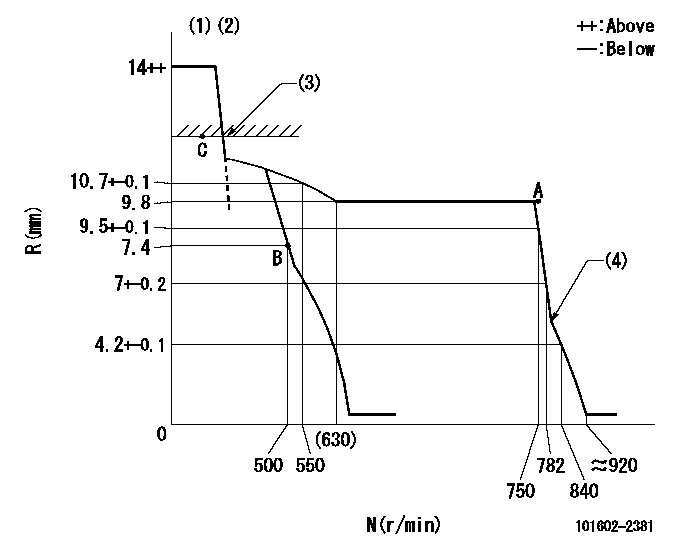
N:Pump speed
R:Rack position (mm)
(1)Target notch: K
(2)Tolerance for racks not indicated: +-0.05mm.
(3)RACK LIMIT
(4)Set idle sub-spring
----------
K=9
----------
----------
K=9
----------
Speed control lever angle
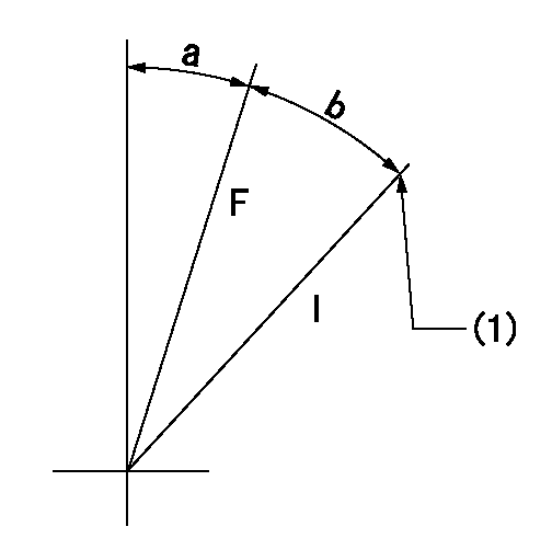
F:Full speed
I:Idle
(1)Stopper bolt setting
----------
----------
a=6deg+-5deg b=10deg+-5deg
----------
----------
a=6deg+-5deg b=10deg+-5deg
Stop lever angle
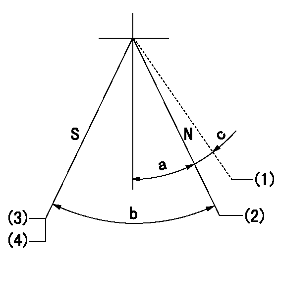
N:Pump normal
S:Stop the pump.
(1)Contacts normal side pin
(2)Distance from normal side pin = aa.
(3)Normal stop
(4)Rack position = bb or less, speed = cc
----------
aa=2.5+-0.5mm bb=6.9mm cc=0r/min
----------
a=27deg+-5deg b=53deg+-5deg c=(6deg)
----------
aa=2.5+-0.5mm bb=6.9mm cc=0r/min
----------
a=27deg+-5deg b=53deg+-5deg c=(6deg)
Timing setting

(1)Pump vertical direction
(2)Position of gear's standard threaded hole at No 1 cylinder's beginning of injection
(3)-
(4)-
----------
----------
a=(70deg)
----------
----------
a=(70deg)
Information:
Illustration 1 g01573105
Typical example (1) Terminal strip (2) Engine oil filler (3) Engine oil cooler (4) Engine oil level gauge (dipstick) (5) Fuel priming pump (6) Expansion tank filler cap (7) Expansion tank (8) Heat exchanger (9) Water pump (jacket water) (10) Engine oil filter (11) Fuel filter
Illustration 2 g01967833
Typical example (12) Filter change indicator (13) Aftercooler (14) Aftercooler condensate drain valve (15) Air cleaner (16) Air filter restriction indicator (17) Sea water pump (18) Fuel transfer pump (19) Filter for crankcase ventilation system (20) Electronic control module (ECM)Starting The Engine
The engine's Electronic Control Module (ECM) will automatically provide the correct amount of fuel in order to start the engine. Do not hold the throttle down while the engine is cranking. If the engine fails to start in 30 seconds, release the starting switch. Allow the starting motor to cool for two minutes before the starting motor is used again.
Excessive ether (starting fluid) can cause piston and ring damage. Use ether for cold weather starting purposes only.
Cold Mode Operation
The ECM will set cold mode when the coolant temperature is below 18 °C (64 °F).When the cold start strategy is activated, low idle rpm will be increased to 1000 rpm and engine power will be limited.Cold mode will be deactivated when the coolant temperature reaches 18 °C (64 °F).
Coolant temperature reaches 18 °C (64 °F).
The engine has been running for fourteen minutes.Cold mode varies the amount of fuel that is injected for white smoke cleanup. Cold mode also varies the timing for white smoke cleanup. The engine operating temperature is usually reached before the walk-around inspection is completed.After cold mode is completed, the engine should be operated at low speed until normal operating temperature is reached. The engine will reach normal operating temperature faster when the engine is operated at low speed and low power demand.Customer Specified Parameters
The engine is capable of being programmed for several customer specified parameters. For a brief explanation of each of the customer specified parameters, see the Operation and Maintenance Manual.