Information injection-pump assembly
BOSCH
F 019 Z10 825
f019z10825
ZEXEL
101602-2380
1016022380
HINO
220203260A
220203260a
Rating:
Service parts 101602-2380 INJECTION-PUMP ASSEMBLY:
1.
_
5.
AUTOM. ADVANCE MECHANIS
6.
COUPLING PLATE
8.
_
9.
_
11.
Nozzle and Holder
236003620A
12.
Open Pre:MPa(Kqf/cm2)
21.6(220)
15.
NOZZLE SET
Cross reference number
BOSCH
F 019 Z10 825
f019z10825
ZEXEL
101602-2380
1016022380
HINO
220203260A
220203260a
Zexel num
Bosch num
Firm num
Name
Calibration Data:
Adjustment conditions
Test oil
1404 Test oil ISO4113 or {SAEJ967d}
1404 Test oil ISO4113 or {SAEJ967d}
Test oil temperature
degC
40
40
45
Nozzle and nozzle holder
105780-8140
Bosch type code
EF8511/9A
Nozzle
105780-0000
Bosch type code
DN12SD12T
Nozzle holder
105780-2080
Bosch type code
EF8511/9
Opening pressure
MPa
17.2
Opening pressure
kgf/cm2
175
Injection pipe
Outer diameter - inner diameter - length (mm) mm 6-2-600
Outer diameter - inner diameter - length (mm) mm 6-2-600
Overflow valve opening pressure
kPa
157
123
191
Overflow valve opening pressure
kgf/cm2
1.6
1.25
1.95
Tester oil delivery pressure
kPa
157
157
157
Tester oil delivery pressure
kgf/cm2
1.6
1.6
1.6
Direction of rotation (viewed from drive side)
Right R
Right R
Injection timing adjustment
Direction of rotation (viewed from drive side)
Right R
Right R
Injection order
1-4-2-6-
3-5
Pre-stroke
mm
3.1
3.05
3.15
Beginning of injection position
Drive side NO.1
Drive side NO.1
Difference between angles 1
Cal 1-4 deg. 60 59.5 60.5
Cal 1-4 deg. 60 59.5 60.5
Difference between angles 2
Cyl.1-2 deg. 120 119.5 120.5
Cyl.1-2 deg. 120 119.5 120.5
Difference between angles 3
Cal 1-6 deg. 180 179.5 180.5
Cal 1-6 deg. 180 179.5 180.5
Difference between angles 4
Cal 1-3 deg. 240 239.5 240.5
Cal 1-3 deg. 240 239.5 240.5
Difference between angles 5
Cal 1-5 deg. 300 299.5 300.5
Cal 1-5 deg. 300 299.5 300.5
Injection quantity adjustment
Adjusting point
A
Rack position
11.2
Pump speed
r/min
750
750
750
Average injection quantity
mm3/st.
58.1
56.1
60.1
Max. variation between cylinders
%
0
-3
3
Basic
*
Fixing the rack
*
Injection quantity adjustment_02
Adjusting point
B
Rack position
8+-0.5
Pump speed
r/min
360
360
360
Average injection quantity
mm3/st.
8.5
7
10
Max. variation between cylinders
%
0
-15
15
Fixing the rack
*
Injection quantity adjustment_03
Adjusting point
C
Rack position
13+-0.5
Pump speed
r/min
100
100
100
Average injection quantity
mm3/st.
72
72
82
Fixing the lever
*
Rack limit
*
Test data Ex:
Governor adjustment
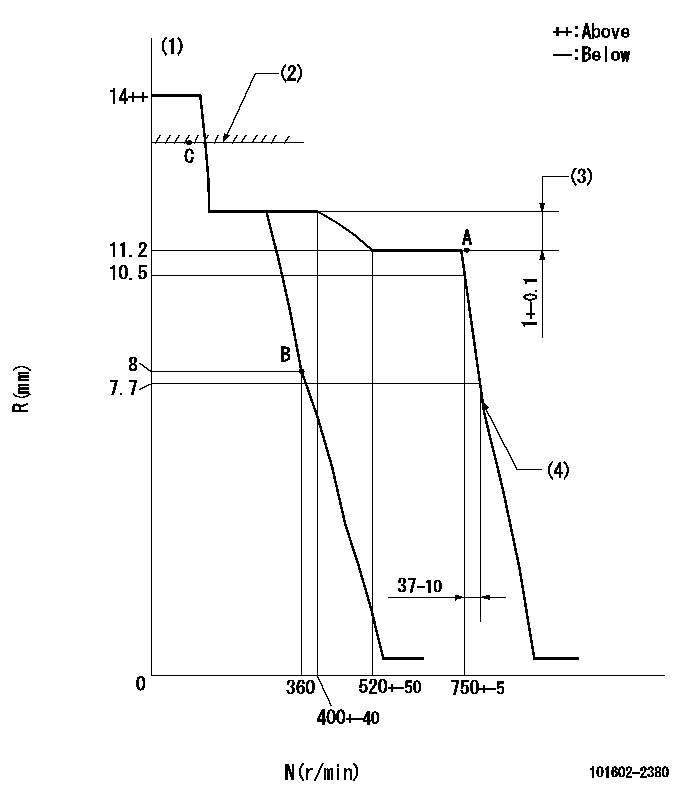
N:Pump speed
R:Rack position (mm)
(1)Target notch: K
(2)RACK LIMIT
(3)Rack difference between N = N1 and N = N2
(4)Idle sub spring setting: L1.
----------
K=4 N1=750r/min N2=350r/min L1=7.1-0.5mm
----------
----------
K=4 N1=750r/min N2=350r/min L1=7.1-0.5mm
----------
Speed control lever angle
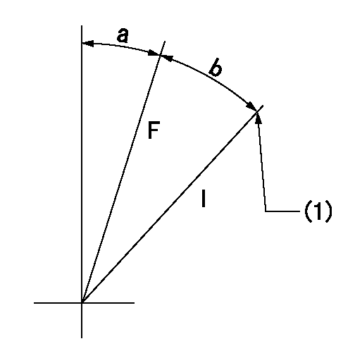
F:Full speed
I:Idle
(1)Stopper bolt setting
----------
----------
a=(7deg)+-5deg b=(13deg)+-5deg
----------
----------
a=(7deg)+-5deg b=(13deg)+-5deg
Stop lever angle
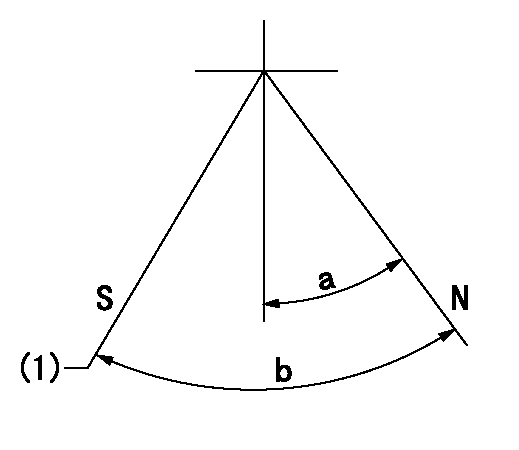
N:Pump normal
S:Stop the pump.
(1)At shipping
----------
----------
a=27deg+-5deg b=53deg+-5deg
----------
----------
a=27deg+-5deg b=53deg+-5deg
Timing setting

(1)Pump vertical direction
(2)Position of gear's standard threaded hole at No 1 cylinder's beginning of injection
(3)-
(4)-
----------
----------
a=(70deg)
----------
----------
a=(70deg)
Information:
Illustration 1 g01096972
Hand priming pump (1) Air purge screw (2) Fuel pressure regulating valve
Open air purge screw (1) for the fuel filter by three full turns. Do not remove the air purge screw.
Do not crank the engine continuously for more than 30 seconds. Allow the starting motor to cool for two minutes before cranking the engine again.
Start the engine. The engine should start and the engine should run smoothly. If the engine does not start after 30 seconds, allow the starting motor to cool for two minutes before attempting to start the engine again.Note: You may use the hand priming pump for the fuel filter (if equipped) instead of starting the engine and running the engine.
While the engine is running, observe air purge screw (1). When a small drop of fuel appears at the threads of the air purge screw, close and tighten air purge screw (1) .Note: There may be a noticeable change in the sound of the running engine when the air purge screw is tightened. The change in the sound of the engine is normal.Note: Failure to tighten all fittings could result in serious fuel leaks.
Clean any residual fuel from the engine components.The Engine Has Been Run Out of Fuel
Use a suitable container to catch any fuel that might spill. Clean up any spilled fuel immediately.
Do not allow dirt to enter the fuel system. Thoroughly clean the area around a fuel system component that will be