Information injection-pump assembly
ZEXEL
101602-2341
1016022341
HINO
220203110A
220203110a
Rating:
Service parts 101602-2341 INJECTION-PUMP ASSEMBLY:
1.
_
5.
AUTOM. ADVANCE MECHANIS
6.
COUPLING PLATE
8.
_
9.
_
11.
Nozzle and Holder
23600-2040
12.
Open Pre:MPa(Kqf/cm2)
21.6{220}
15.
NOZZLE SET
Cross reference number
ZEXEL
101602-2341
1016022341
HINO
220203110A
220203110a
Zexel num
Bosch num
Firm num
Name
Calibration Data:
Adjustment conditions
Test oil
1404 Test oil ISO4113 or {SAEJ967d}
1404 Test oil ISO4113 or {SAEJ967d}
Test oil temperature
degC
40
40
45
Nozzle and nozzle holder
105780-8140
Bosch type code
EF8511/9A
Nozzle
105780-0000
Bosch type code
DN12SD12T
Nozzle holder
105780-2080
Bosch type code
EF8511/9
Opening pressure
MPa
17.2
Opening pressure
kgf/cm2
175
Injection pipe
Outer diameter - inner diameter - length (mm) mm 6-2-600
Outer diameter - inner diameter - length (mm) mm 6-2-600
Overflow valve
131424-5720
Overflow valve opening pressure
kPa
255
221
289
Overflow valve opening pressure
kgf/cm2
2.6
2.25
2.95
Tester oil delivery pressure
kPa
157
157
157
Tester oil delivery pressure
kgf/cm2
1.6
1.6
1.6
Direction of rotation (viewed from drive side)
Right R
Right R
Injection timing adjustment
Direction of rotation (viewed from drive side)
Right R
Right R
Injection order
1-4-2-6-
3-5
Pre-stroke
mm
3.1
3.05
3.15
Beginning of injection position
Drive side NO.1
Drive side NO.1
Difference between angles 1
Cal 1-4 deg. 60 59.5 60.5
Cal 1-4 deg. 60 59.5 60.5
Difference between angles 2
Cyl.1-2 deg. 120 119.5 120.5
Cyl.1-2 deg. 120 119.5 120.5
Difference between angles 3
Cal 1-6 deg. 180 179.5 180.5
Cal 1-6 deg. 180 179.5 180.5
Difference between angles 4
Cal 1-3 deg. 240 239.5 240.5
Cal 1-3 deg. 240 239.5 240.5
Difference between angles 5
Cal 1-5 deg. 300 299.5 300.5
Cal 1-5 deg. 300 299.5 300.5
Injection quantity adjustment
Adjusting point
A
Rack position
9.5
Pump speed
r/min
800
800
800
Average injection quantity
mm3/st.
46.2
45.2
47.2
Max. variation between cylinders
%
0
-3
3
Basic
*
Fixing the lever
*
Injection quantity adjustment_02
Adjusting point
B
Rack position
9.3
Pump speed
r/min
1150
1150
1150
Average injection quantity
mm3/st.
49
48
50
Fixing the rack
*
Injection quantity adjustment_03
Adjusting point
D
Rack position
8+-0.5
Pump speed
r/min
350
350
350
Average injection quantity
mm3/st.
8.2
6.7
9.7
Max. variation between cylinders
%
0
-15
15
Fixing the rack
*
Injection quantity adjustment_04
Adjusting point
E
Rack position
-
Pump speed
r/min
100
100
100
Average injection quantity
mm3/st.
95
95
105
Fixing the lever
*
Rack limit
*
Test data Ex:
Governor adjustment
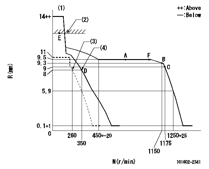
N:Pump speed
R:Rack position (mm)
(1)Target notch: K
(2)RACK LIMIT
(3)Set idle sub-spring
(4)Main spring setting
----------
K=6
----------
----------
K=6
----------
Speed control lever angle
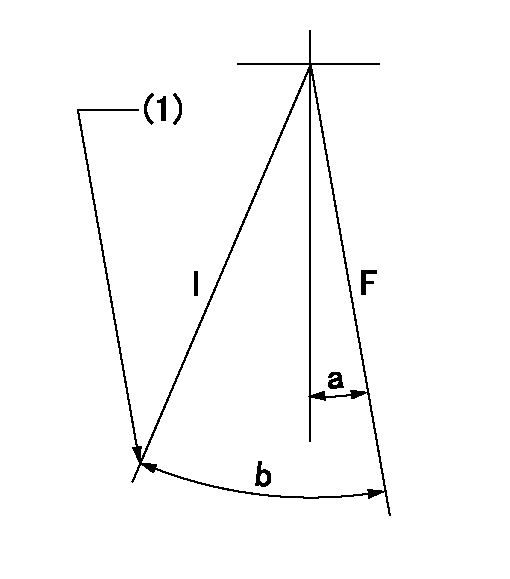
F:Full speed
I:Idle
(1)Stopper bolt setting
----------
----------
a=4deg+-5deg b=20deg+-5deg
----------
----------
a=4deg+-5deg b=20deg+-5deg
Stop lever angle

N:Pump normal
S:Stop the pump.
----------
----------
a=27deg+-5deg b=53deg+-5deg
----------
----------
a=27deg+-5deg b=53deg+-5deg
Timing setting

(1)Pump vertical direction
(2)Position of gear's standard threaded hole at No 1 cylinder's beginning of injection
(3)-
(4)-
----------
----------
a=(70deg)
----------
----------
a=(70deg)
Information:
Illustration 1 g02004767
(1) Ring for Identification (2) 228-7094 O-Ring Seal (3) 345-3399 Injector Sleeve An oversized injector sleeve will be introduced in order to improve the life cycle of the cylinder heads. The new sleeve has an oversized outside diameter, which does not allow the injector sleeve to fit the standard bore. The oversized sleeve will have an added ring that is located around the middle of the insert for identification. Also, the new sleeve will require a larger bottom O-ring. Refer to Illustration 1.
Illustration 2 g02004793
(4) Identification markThe remanufactured cylinder head has an identification mark that is located on the top of the cylinder head. This mark indicates the cylinders that have the oversized inserts.