Information injection-pump assembly
ZEXEL
101602-2260
1016022260
HINO
220202830A
220202830a

Rating:
Cross reference number
ZEXEL
101602-2260
1016022260
HINO
220202830A
220202830a
Zexel num
Bosch num
Firm num
Name
Calibration Data:
Adjustment conditions
Test oil
1404 Test oil ISO4113 or {SAEJ967d}
1404 Test oil ISO4113 or {SAEJ967d}
Test oil temperature
degC
40
40
45
Nozzle and nozzle holder
105780-8140
Bosch type code
EF8511/9A
Nozzle
105780-0000
Bosch type code
DN12SD12T
Nozzle holder
105780-2080
Bosch type code
EF8511/9
Opening pressure
MPa
17.2
Opening pressure
kgf/cm2
175
Injection pipe
Outer diameter - inner diameter - length (mm) mm 6-2-600
Outer diameter - inner diameter - length (mm) mm 6-2-600
Overflow valve
134424-0920
Overflow valve opening pressure
kPa
162
147
177
Overflow valve opening pressure
kgf/cm2
1.65
1.5
1.8
Tester oil delivery pressure
kPa
157
157
157
Tester oil delivery pressure
kgf/cm2
1.6
1.6
1.6
Direction of rotation (viewed from drive side)
Right R
Right R
Injection timing adjustment
Direction of rotation (viewed from drive side)
Right R
Right R
Injection order
1-4-2-6-
3-5
Pre-stroke
mm
2.8
2.77
2.83
Beginning of injection position
Drive side NO.1
Drive side NO.1
Difference between angles 1
Cal 1-4 deg. 60 59.75 60.25
Cal 1-4 deg. 60 59.75 60.25
Difference between angles 2
Cyl.1-2 deg. 120 119.75 120.25
Cyl.1-2 deg. 120 119.75 120.25
Difference between angles 3
Cal 1-6 deg. 180 179.75 180.25
Cal 1-6 deg. 180 179.75 180.25
Difference between angles 4
Cal 1-3 deg. 240 239.75 240.25
Cal 1-3 deg. 240 239.75 240.25
Difference between angles 5
Cal 1-5 deg. 300 299.75 300.25
Cal 1-5 deg. 300 299.75 300.25
Injection quantity adjustment
Adjusting point
B
Rack position
9.3
Pump speed
r/min
900
900
900
Average injection quantity
mm3/st.
83.8
82.8
84.8
Max. variation between cylinders
%
0
-3.5
3.5
Fixing the lever
*
Boost pressure
kPa
26
26
Boost pressure
mmHg
195
195
Injection quantity adjustment_02
Adjusting point
D
Rack position
R1(6.5)
Pump speed
r/min
410
410
410
Average injection quantity
mm3/st.
9.6
8.6
10.6
Max. variation between cylinders
%
0
-10
10
Fixing the rack
*
Boost pressure
kPa
0
0
0
Boost pressure
mmHg
0
0
0
Injection quantity adjustment_03
Adjusting point
E
Rack position
12.6+-0.
5
Pump speed
r/min
100
100
100
Average injection quantity
mm3/st.
135
135
145
Fixing the lever
*
Rack limit
*
Boost compensator adjustment
Pump speed
r/min
600
600
600
Rack position
8.5
Boost pressure
kPa
9.3
8
10.6
Boost pressure
mmHg
70
60
80
Boost compensator adjustment_02
Pump speed
r/min
600
600
600
Rack position
9.3
Boost pressure
kPa
16.7
16.7
16.7
Boost pressure
mmHg
125
125
125
Test data Ex:
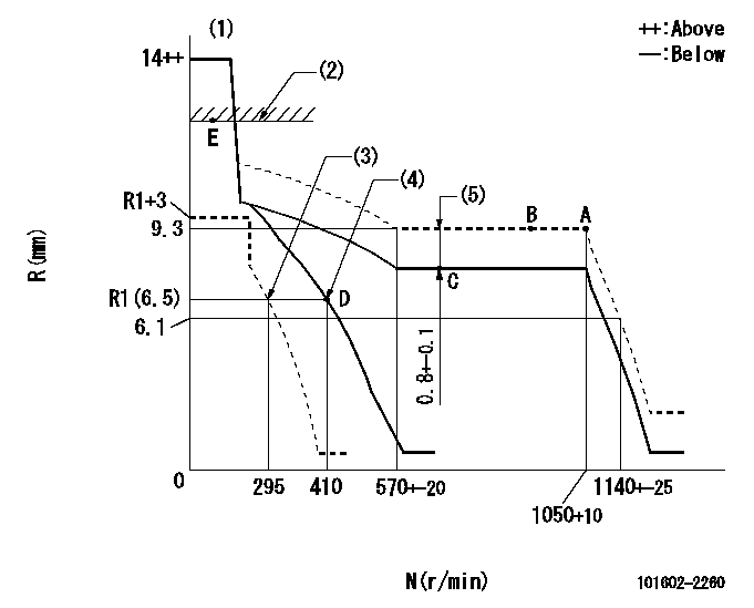
Governor adjustment

N:Pump speed
R:Rack position (mm)
(1)Target notch: K
(2)RACK LIMIT
(3)Set idle sub-spring
(4)Main spring setting
(5)Boost compensator stroke
----------
K=7
----------
----------
K=7
----------
Speed control lever angle

F:Full speed
I:Idle
(1)Stopper bolt setting
----------
----------
a=(1deg)+-5deg b=(17deg)+-5deg
----------
----------
a=(1deg)+-5deg b=(17deg)+-5deg
Stop lever angle

N:Pump normal
S:Stop the pump.
(1)Speed = aa, rack position = bb (sealed at shipping)
----------
aa=0r/min bb=1-0.2mm
----------
a=21deg+-5deg b=(55deg)
----------
aa=0r/min bb=1-0.2mm
----------
a=21deg+-5deg b=(55deg)
Timing setting

(1)Pump vertical direction
(2)Coupling's key groove position at No 1 cylinder's beginning of injection
(3)-
(4)-
----------
----------
a=(55deg)
----------
----------
a=(55deg)
Information:
Disassembly
The following tools are needed: torque wrench, 16 millimeter socket or wrench, cotton swabs, rubbing alcohol, rubber gloves, small magnet, flashlight, plastic spray bottle and molykote or white lithium greaseThe following parts are supplied: two plugs for the outlet check valves, two outlet check valves, two springs and two ball studs
Ensure the proper cleanliness of hands and all parts before you begin the service procedure.
Check the engine serial number in order to ensure that the engine is correct for the service letter.
Steam clean the area that surrounds the plug for the outlet check valve or clean the area around the plug for the outlet check valve by flushing with rubbing alcohol.
The area must be cleaned with a towel that is soaked with alcohol in order to remove any other debris.
Inspect the area that is surrounding the plug for the outlet check valve in order to ensure that no debris is present.
Illustration 1 g01618509
Using a clean 16 millimeter socket or a wrench remove the plug for the outlet check valve.
Carefully remove the plug from the pump head. The spring is removed with the plug.
If the outlet check valve remains in the head, remove the check valve with the clean magnet.
Clean the threads and the area around the plug.Note: Soak the cotton swab with alcohol and insert the cotton swab into the threaded area. Use a counterclockwise rotation to clean the threaded area. Clean the spot face around the plug bore with a cotton swab that is soaked in alcohol. Clean the spot face around the plug bore in a counterclockwise rotation.
Illustration 2 g01626597
(1) Sealing surface of the pump bore
Look inside the pump bore in order to ensure that no debris that includes the debris from the cotton swab is on the sealing surface.
Repeat until the cotton swab is free of debris.
Illustration 3 g01618506
Assembly
Once parts have been removed, clean hands and put on clean rubber gloves.
When the parts are being installed in the pump, flush all the new parts with alcohol in order to ensure that no debris is on the parts.
Use a clean finger to apply clean molykote or white lithium grease to the surface that is being sealed and threads of plug.
Illustration 4 g01624087
Use clean molykote or white lithium grease in order to install the ball stud on the end of the spring. Press the ball stud and the spring together.
Illustration 5 g01624092
Insert the subassembly of the ball stud and the spring into the plug for the outlet check valve, with the end with the ball stud in the plug.Note: Be careful not to scratch the sealing surface of the plug for the outlet check valve.
Illustration 6 g01626602
(2) Sealing surface of the plug for the outlet check valve
Illustration 7 g01624154
(3) Gauge Pin
Illustration 8 g01624824
(4) Location of the ring groove on the gauge pin on a properly assembled ball stud and spring assembly
The distance between the end of the spring and the sealing surface of the plug for the outlet check valve should be checked with a gauge pin. The ring groove must be above the top