Information injection-pump assembly
BOSCH
9 400 614 758
9400614758
ZEXEL
101602-2193
1016022193
HINO
220202583A
220202583a
Rating:
Service parts 101602-2193 INJECTION-PUMP ASSEMBLY:
1.
_
5.
AUTOM. ADVANCE MECHANIS
6.
COUPLING PLATE
8.
_
9.
_
11.
Nozzle and Holder
23600-1580
12.
Open Pre:MPa(Kqf/cm2)
21.6{220}
15.
NOZZLE SET
Cross reference number
BOSCH
9 400 614 758
9400614758
ZEXEL
101602-2193
1016022193
HINO
220202583A
220202583a
Zexel num
Bosch num
Firm num
Name
101602-2193
9 400 614 758
220202583A HINO
INJECTION-PUMP ASSEMBLY
W06D * K
W06D * K
101602-2193
9 400 614 758
S220202583A HINO
INJECTION-PUMP ASSEMBLY
W06D A * K
W06D A * K
Calibration Data:
Adjustment conditions
Test oil
1404 Test oil ISO4113 or {SAEJ967d}
1404 Test oil ISO4113 or {SAEJ967d}
Test oil temperature
degC
40
40
45
Nozzle and nozzle holder
105780-8140
Bosch type code
EF8511/9A
Nozzle
105780-0000
Bosch type code
DN12SD12T
Nozzle holder
105780-2080
Bosch type code
EF8511/9
Opening pressure
MPa
17.2
Opening pressure
kgf/cm2
175
Injection pipe
Outer diameter - inner diameter - length (mm) mm 6-2-600
Outer diameter - inner diameter - length (mm) mm 6-2-600
Overflow valve
131424-5720
Overflow valve opening pressure
kPa
255
221
289
Overflow valve opening pressure
kgf/cm2
2.6
2.25
2.95
Tester oil delivery pressure
kPa
157
157
157
Tester oil delivery pressure
kgf/cm2
1.6
1.6
1.6
Direction of rotation (viewed from drive side)
Right R
Right R
Injection timing adjustment
Direction of rotation (viewed from drive side)
Right R
Right R
Injection order
1-4-2-6-
3-5
Pre-stroke
mm
3.1
3.05
3.15
Beginning of injection position
Drive side NO.1
Drive side NO.1
Difference between angles 1
Cal 1-4 deg. 60 59.5 60.5
Cal 1-4 deg. 60 59.5 60.5
Difference between angles 2
Cyl.1-2 deg. 120 119.5 120.5
Cyl.1-2 deg. 120 119.5 120.5
Difference between angles 3
Cal 1-6 deg. 180 179.5 180.5
Cal 1-6 deg. 180 179.5 180.5
Difference between angles 4
Cal 1-3 deg. 240 239.5 240.5
Cal 1-3 deg. 240 239.5 240.5
Difference between angles 5
Cal 1-5 deg. 300 299.5 300.5
Cal 1-5 deg. 300 299.5 300.5
Injection quantity adjustment
Adjusting point
A
Rack position
9.8
Pump speed
r/min
750
750
750
Average injection quantity
mm3/st.
45.3
43.3
47.3
Max. variation between cylinders
%
0
-3
3
Basic
*
Fixing the rack
*
Injection quantity adjustment_02
Adjusting point
-
Rack position
7.8+-0.5
Pump speed
r/min
500
500
500
Average injection quantity
mm3/st.
9
7.5
10.5
Max. variation between cylinders
%
0
-15
15
Fixing the rack
*
Remarks
Adjust only variation between cylinders; adjust governor according to governor specifications.
Adjust only variation between cylinders; adjust governor according to governor specifications.
Injection quantity adjustment_03
Adjusting point
C
Rack position
-
Pump speed
r/min
100
100
100
Average injection quantity
mm3/st.
63
63
73
Fixing the lever
*
Rack limit
*
Test data Ex:
Governor adjustment
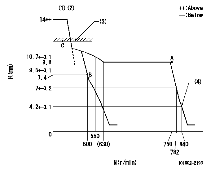
N:Pump speed
R:Rack position (mm)
(1)Target notch: K
(2)Tolerance for racks not indicated: +-0.05mm.
(3)RACK LIMIT
(4)Set idle sub-spring
----------
K=9
----------
----------
K=9
----------
Speed control lever angle
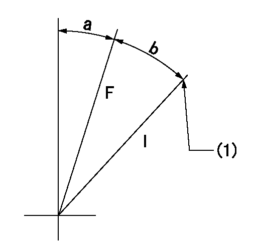
F:Full speed
I:Idle
(1)Stopper bolt setting
----------
----------
a=6deg+-5deg b=10deg+-5deg
----------
----------
a=6deg+-5deg b=10deg+-5deg
Stop lever angle
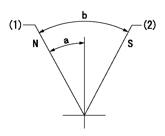
N:Pump normal
S:Stop the pump.
(1)Normal
(2)Rack position = aa or less, at speed = bb
----------
aa=6.9mm bb=0r/min
----------
a=27deg+-5deg b=53deg+-5deg
----------
aa=6.9mm bb=0r/min
----------
a=27deg+-5deg b=53deg+-5deg
Timing setting

(1)Pump vertical direction
(2)Position of gear's standard threaded hole at No 1 cylinder's beginning of injection
(3)-
(4)-
----------
----------
a=(70deg)
----------
----------
a=(70deg)
Information:
Introduction
Diesel Particulate Filters (DPF) and Catalytic Converter Mufflers (CCM) are not applicable to all engines. Some engines contain a DPF and a CCM device that were installed as original equipment to meet engine emissions certification requirements. However, some engines may have had the devices installed during a retrofit program for emissions reduction.
Do not perform any procedure in this Special Instruction until you read this information and you understand this information.Procedure for Shipping the Diesel Particulate Filters (DPF)
Wear goggles, gloves, protective clothing, and a National Institute for Occupational Safety and Health (NIOSH) approved P95 or N95 half-face respirator when handling a used Diesel Particulate Filter or Catalytic Converter Muffler. Failure to do so could result in personal injury.
Place all the used Diesel Particulate Filter (DPF) center sections, regardless of condition, into a 0.152 mm (0.006 inch) thick plastic bag. Make sure that the bag is sealed before placing the DPF into a shipping container. This must be performed in order to contain any constituents from the used DPF during shipping. New replacement diesel particulate filters may come with a 0.152 mm (0.006 inch) plastic bag that can be used for wrapping the used DPF.Procedure for Shipping the Catalytic Converter Mufflers (CCM)
Seal the inlet port and the outlet port on all used Catalytic Converter Mufflers (CCM) with rubber caps or plastic caps. Various sized plastic caps can be ordered from the Cat Shop Supplies and Hand Tools catalog. Reference caps and plugs under the Shop Supplies section. An alternative is to seal the inlet ports and outlet ports with a 0.152 mm (0.006 inch) thick sheet of plastic and 50 mm (2 inch) wide sealing tape with good adhesive properties before shipping. Sealing or capping must be performed in order to contain any constituents from the used CCM during shipping.
Have questions with 101602-2193?
Group cross 101602-2193 ZEXEL
Hino
101602-2193
9 400 614 758
220202583A
INJECTION-PUMP ASSEMBLY
W06D
W06D
101602-2193
9 400 614 758
S220202583A
INJECTION-PUMP ASSEMBLY
W06D
W06D