Information injection-pump assembly
BOSCH
F 019 Z10 824
f019z10824
ZEXEL
101602-2192
1016022192
HINO
220202582A
220202582a
Rating:
Service parts 101602-2192 INJECTION-PUMP ASSEMBLY:
1.
_
5.
AUTOM. ADVANCE MECHANIS
6.
COUPLING PLATE
8.
_
9.
_
11.
Nozzle and Holder
236003620A
12.
Open Pre:MPa(Kqf/cm2)
21.6(220)
15.
NOZZLE SET
Cross reference number
BOSCH
F 019 Z10 824
f019z10824
ZEXEL
101602-2192
1016022192
HINO
220202582A
220202582a
Zexel num
Bosch num
Firm num
Name
Calibration Data:
Adjustment conditions
Test oil
1404 Test oil ISO4113 or {SAEJ967d}
1404 Test oil ISO4113 or {SAEJ967d}
Test oil temperature
degC
40
40
45
Nozzle and nozzle holder
105780-8140
Bosch type code
EF8511/9A
Nozzle
105780-0000
Bosch type code
DN12SD12T
Nozzle holder
105780-2080
Bosch type code
EF8511/9
Opening pressure
MPa
17.2
Opening pressure
kgf/cm2
175
Injection pipe
Outer diameter - inner diameter - length (mm) mm 6-2-600
Outer diameter - inner diameter - length (mm) mm 6-2-600
Overflow valve opening pressure
kPa
157
123
191
Overflow valve opening pressure
kgf/cm2
1.6
1.25
1.95
Tester oil delivery pressure
kPa
157
157
157
Tester oil delivery pressure
kgf/cm2
1.6
1.6
1.6
Direction of rotation (viewed from drive side)
Right R
Right R
Injection timing adjustment
Direction of rotation (viewed from drive side)
Right R
Right R
Injection order
1-4-2-6-
3-5
Pre-stroke
mm
3.1
3.05
3.15
Beginning of injection position
Drive side NO.1
Drive side NO.1
Difference between angles 1
Cal 1-4 deg. 60 59.5 60.5
Cal 1-4 deg. 60 59.5 60.5
Difference between angles 2
Cyl.1-2 deg. 120 119.5 120.5
Cyl.1-2 deg. 120 119.5 120.5
Difference between angles 3
Cal 1-6 deg. 180 179.5 180.5
Cal 1-6 deg. 180 179.5 180.5
Difference between angles 4
Cal 1-3 deg. 240 239.5 240.5
Cal 1-3 deg. 240 239.5 240.5
Difference between angles 5
Cal 1-5 deg. 300 299.5 300.5
Cal 1-5 deg. 300 299.5 300.5
Injection quantity adjustment
Adjusting point
A
Rack position
11.2
Pump speed
r/min
750
750
750
Average injection quantity
mm3/st.
58.1
56.1
60.1
Max. variation between cylinders
%
0
-3
3
Basic
*
Fixing the rack
*
Injection quantity adjustment_02
Adjusting point
B
Rack position
8+-0.5
Pump speed
r/min
360
360
360
Average injection quantity
mm3/st.
8.5
7
10
Max. variation between cylinders
%
0
-15
15
Fixing the rack
*
Injection quantity adjustment_03
Adjusting point
C
Rack position
13+-0.5
Pump speed
r/min
100
100
100
Average injection quantity
mm3/st.
72
72
82
Fixing the lever
*
Rack limit
*
Test data Ex:
Governor adjustment
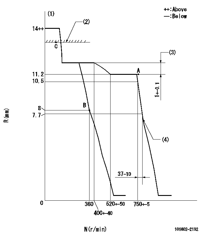
N:Pump speed
R:Rack position (mm)
(1)Target notch: K
(2)RACK LIMIT
(3)Rack difference between N = N1 and N = N2
(4)Idle sub spring setting: L1.
----------
K=4 N1=750r/min N2=350r/min L1=7.1-0.5mm
----------
----------
K=4 N1=750r/min N2=350r/min L1=7.1-0.5mm
----------
Speed control lever angle
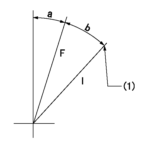
F:Full speed
I:Idle
(1)Stopper bolt setting
----------
----------
a=(7deg)+-5deg b=(13deg)+-5deg
----------
----------
a=(7deg)+-5deg b=(13deg)+-5deg
Stop lever angle

N:Pump normal
S:Stop the pump.
----------
----------
a=27deg+-5deg b=53deg+-5deg
----------
----------
a=27deg+-5deg b=53deg+-5deg
Timing setting

(1)Pump vertical direction
(2)Position of gear's standard threaded hole at No 1 cylinder's beginning of injection
(3)-
(4)-
----------
----------
a=(70deg)
----------
----------
a=(70deg)
Information:
Illustration 1 g01491433
Measuring the outer diameter of the center section of the DPF
Illustration 2 g01756814
DPF flange designs (B) Standard flange (C) Submerged flange
Measure the outer diameter of the center section of the DPF. Illustration 1 shows the outer diameter of the center section of the DPF. Use Table 2 to locate the appropriate cone and the proper adapters for your application.Note: These adapters are part of the 319-2189 Diesel Particulate Filter Cleaner Gp .
Table 2
Model and Description for the DPF Outer Diameter of the Center Section of the DPF
"A" Large Cone
319-1836 Medium Cone
319-1835 Small Cone
319-2192 Upper Adapter for Mass Transit Buses (MTB)
319-2192 Lower Adapter
319-1838 Lower Adapter
319-1839 Gasket Part Number
(mm) (inches)
9.5 x 14 Submerged 253.1 10 X X 293-6156
9.5 x 14 Standard 279.3 11 X X 279-3259
11.25 x 14 Submerged 279.3 11 X X 279-3259
264-1556 Filter Module As MTB 318.2 12.5 X X X 247-1899
11.25 x 14
MTB Standard 321.1 12.6 X X 279-1081
13 x 15 or 13 x 17 Submerged 342.8 13.5 X X 279-2123
12 x 15 342.8 13.5 X X 279-2123
13 x 15 or 13 x 17Standard 368.2 14.5 X X 278-5711 Note: All the pressure ports and the thermocouple ports on the DPF must be plugged before cleaning.
Illustration 3 g01491993
Plug any other open ports on the DPF.
Install a 2F-2990 Seal Plug or a 102-9379 Plug in all the open ports on the DPF.
Assemble the DPF. Refer to the engine Disassembly and Assembly Manual, "Diesel Particulate Filter - Assemble" for the proper procedure to assemble the DPF.
Reinstall the DPF onto the vehicle.Ash Service Reset
The engine ash model must be reset whenever the filter is cleaned or replaced. This resets the DPF volume back to the "Clean State". The resetting will allow the regeneration of the DPF to function properly.
Use Cat ET to access the configuration parameters. In the "System Settings" group of parameters, highlight the" Diesel Particulate Filter Ash Service Reset". Refer to Illustration 4 for the location of the " Diesel Particulate Filter Ash Service Reset". The value of the parameter should be "Not Reset".
Click the "Change" button at the bottom of the screen. The change will require the Factory Passwords to be reset. Enter "Reason code 67".
Enter the