Information injection-pump assembly
ZEXEL
101602-2182
1016022182
HINO
220202261A
220202261a
Rating:
Service parts 101602-2182 INJECTION-PUMP ASSEMBLY:
1.
_
5.
AUTOM. ADVANCE MECHANIS
6.
COUPLING PLATE
8.
_
9.
_
11.
Nozzle and Holder
23600-1580
12.
Open Pre:MPa(Kqf/cm2)
21.6{220}
15.
NOZZLE SET
Cross reference number
ZEXEL
101602-2182
1016022182
HINO
220202261A
220202261a
Zexel num
Bosch num
Firm num
Name
Calibration Data:
Adjustment conditions
Test oil
1404 Test oil ISO4113 or {SAEJ967d}
1404 Test oil ISO4113 or {SAEJ967d}
Test oil temperature
degC
40
40
45
Nozzle and nozzle holder
105780-8140
Bosch type code
EF8511/9A
Nozzle
105780-0000
Bosch type code
DN12SD12T
Nozzle holder
105780-2080
Bosch type code
EF8511/9
Opening pressure
MPa
17.2
Opening pressure
kgf/cm2
175
Injection pipe
Outer diameter - inner diameter - length (mm) mm 6-2-600
Outer diameter - inner diameter - length (mm) mm 6-2-600
Overflow valve opening pressure
kPa
157
123
191
Overflow valve opening pressure
kgf/cm2
1.6
1.25
1.95
Tester oil delivery pressure
kPa
157
157
157
Tester oil delivery pressure
kgf/cm2
1.6
1.6
1.6
Direction of rotation (viewed from drive side)
Right R
Right R
Injection timing adjustment
Direction of rotation (viewed from drive side)
Right R
Right R
Injection order
1-4-2-6-
3-5
Pre-stroke
mm
3.1
3.05
3.15
Beginning of injection position
Drive side NO.1
Drive side NO.1
Difference between angles 1
Cal 1-4 deg. 60 59.5 60.5
Cal 1-4 deg. 60 59.5 60.5
Difference between angles 2
Cyl.1-2 deg. 120 119.5 120.5
Cyl.1-2 deg. 120 119.5 120.5
Difference between angles 3
Cal 1-6 deg. 180 179.5 180.5
Cal 1-6 deg. 180 179.5 180.5
Difference between angles 4
Cal 1-3 deg. 240 239.5 240.5
Cal 1-3 deg. 240 239.5 240.5
Difference between angles 5
Cal 1-5 deg. 300 299.5 300.5
Cal 1-5 deg. 300 299.5 300.5
Injection quantity adjustment
Adjusting point
A
Rack position
10.5
Pump speed
r/min
900
900
900
Average injection quantity
mm3/st.
52.1
50.1
54.1
Max. variation between cylinders
%
0
-3
3
Basic
*
Fixing the rack
*
Injection quantity adjustment_02
Adjusting point
B
Rack position
11.2
Pump speed
r/min
750
750
750
Average injection quantity
mm3/st.
58.1
55.1
61.1
Max. variation between cylinders
%
0
-4
4
Fixing the lever
*
Injection quantity adjustment_03
Adjusting point
C
Rack position
8+-0.5
Pump speed
r/min
360
360
360
Average injection quantity
mm3/st.
8.5
7
10
Max. variation between cylinders
%
0
-15
15
Fixing the rack
*
Injection quantity adjustment_04
Adjusting point
D
Rack position
13+-0.5
Pump speed
r/min
100
100
100
Average injection quantity
mm3/st.
72
72
82
Fixing the lever
*
Rack limit
*
Test data Ex:
Governor adjustment
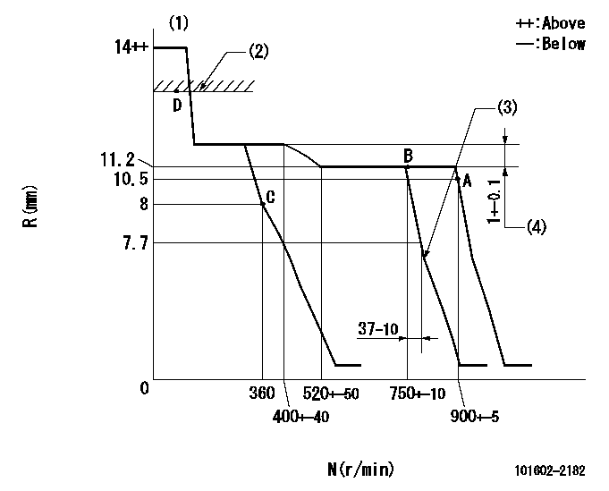
N:Pump speed
R:Rack position (mm)
(1)Target notch: K
(2)RACK LIMIT
(3)Idle sub spring setting: L1.
(4)Rack difference between N = N1 and N = N2
----------
K=4 L1=7.1-0.5mm N1=750r/min N2=350r/min
----------
----------
K=4 L1=7.1-0.5mm N1=750r/min N2=350r/min
----------
Speed control lever angle
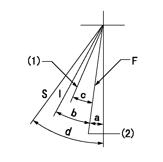
F:Full speed
I:Idle
S:Stop
(1)Set the pump speed at aa
(2)Set the pump speed at bb (at delivery)
----------
aa=750r/min bb=900r/min
----------
a=(2deg)+-5deg b=(18deg)+-5deg c=(5deg)+-5deg d=32deg+-3deg
----------
aa=750r/min bb=900r/min
----------
a=(2deg)+-5deg b=(18deg)+-5deg c=(5deg)+-5deg d=32deg+-3deg
Stop lever angle

N:Pump normal
S:Stop the pump.
----------
----------
a=27deg+-5deg b=53deg+-5deg
----------
----------
a=27deg+-5deg b=53deg+-5deg
Timing setting

(1)Pump vertical direction
(2)Position of gear's standard threaded hole at No 1 cylinder's beginning of injection
(3)-
(4)-
----------
----------
a=(70deg)
----------
----------
a=(70deg)
Information:
Table 1
Required Parts
Item Qty Part Number Description Former Part Number
1 1 560-4252 Bracket 431-8663
2 1 396-3862 (1) Control Harness As 396-3862 (1)
524-5527 (2) Control Harness As 524-5527 (2)
3 1 471-4176 Hose As 380-9241
4 - 7K-1181 Cable Strap NA
5 - 3E-6909 Clip NA
(1) FMC 1 - 772 (Not Equipped with DEF Quality Sensor)
(2) FMC 773 - Up (Equipped with DEF Quality Sensor)Note: These parts should be ordered and replaced only if there is evidence of damage to any part.Rework Procedure
Park the machine on level ground, lower all implements to the ground, shut off machine, and relieve all hydraulic system pressure.
Read and understand this Rework Procedure before starting work.
Illustration 1 g06340431
General location and reference Views
DEF tank cover not shown for clarity.
(A) Fuel tank
(B) Diesel Exhaust Fluid (DEF) module group
See Illustration for the general location of the DEF Module Group and reference views that will be used in future steps.
Illustration 2 g06340436
Location of hardware.
(C) Hardware
(D) DEF fill hose
(E) Clamp
Inspect control harness assembly (2) at location (AA) and hose assembly (3) at location (BB) for rubbing and or fouling on the DEF Tank Cover. If either item is damaged, replace the damaged part.Note: Hardware (C) holding the DEF Module Group to the fuel tank and clamp (E) holding DEF Fill Hose (D) to the tank will need to be loosened to reposition the DEF Module Group to access control harness assembly (2) and hose assembly (3).
After control harness assembly (2) and hose assembly (3) have been inspected and found without damage OR replaced, secure both parts using Steps 6 through 9.
Illustration 3 g06340441
Left view
Fuel tank not shown.
(F) Diesel exhaust fluid module
Illustration 4 g06340446
Location CC
(G) Harness bundled to avoid fouling
Illustration 5 g06340447
Location DD
(H) Terminating resistor
Secure control harness assembly (2) and hose assembly (3) to left side of DEF Module using tie straps (4).Reference: Refer to Illustrations 3, 4, and 5.Note: At location (CC), use tie straps to secure harness bundles to prevent harness from contacting the fuel tank. (See Illustration 4).Note: At location (DD), use tie straps (4) to secure control harness assembly (2) and hose assembly (3), and terminating resistor (H) at lower location. (See Illustration 5).
Illustration 6 g06340448
Location of hardware
(C) Hardware
(E) Clamp
Reposition the DEF Module Group, install bracket (1), and reinstall the remaining hardware (C), clamp (E) removed in Step 4. Check to make sure control harness assembly (2) and hose assembly (3) will not