Information injection-pump assembly
BOSCH
9 400 614 754
9400614754
ZEXEL
101602-2153
1016022153
HINO
220202013A
220202013a
Rating:
Service parts 101602-2153 INJECTION-PUMP ASSEMBLY:
1.
_
5.
AUTOM. ADVANCE MECHANIS
6.
COUPLING PLATE
8.
_
9.
_
11.
Nozzle and Holder
23600-1593A
12.
Open Pre:MPa(Kqf/cm2)
21.6{220}
15.
NOZZLE SET
Cross reference number
BOSCH
9 400 614 754
9400614754
ZEXEL
101602-2153
1016022153
HINO
220202013A
220202013a
Zexel num
Bosch num
Firm num
Name
101602-2153
9 400 614 754
220202013A HINO
INJECTION-PUMP ASSEMBLY
W06D * K
W06D * K
Calibration Data:
Adjustment conditions
Test oil
1404 Test oil ISO4113 or {SAEJ967d}
1404 Test oil ISO4113 or {SAEJ967d}
Test oil temperature
degC
40
40
45
Nozzle and nozzle holder
105780-8140
Bosch type code
EF8511/9A
Nozzle
105780-0000
Bosch type code
DN12SD12T
Nozzle holder
105780-2080
Bosch type code
EF8511/9
Opening pressure
MPa
17.2
Opening pressure
kgf/cm2
175
Injection pipe
Outer diameter - inner diameter - length (mm) mm 6-2-600
Outer diameter - inner diameter - length (mm) mm 6-2-600
Overflow valve
131424-5720
Overflow valve opening pressure
kPa
255
221
289
Overflow valve opening pressure
kgf/cm2
2.6
2.25
2.95
Tester oil delivery pressure
kPa
157
157
157
Tester oil delivery pressure
kgf/cm2
1.6
1.6
1.6
Direction of rotation (viewed from drive side)
Right R
Right R
Injection timing adjustment
Direction of rotation (viewed from drive side)
Right R
Right R
Injection order
1-4-2-6-
3-5
Pre-stroke
mm
3.1
3.05
3.15
Beginning of injection position
Drive side NO.1
Drive side NO.1
Difference between angles 1
Cal 1-4 deg. 60 59.5 60.5
Cal 1-4 deg. 60 59.5 60.5
Difference between angles 2
Cyl.1-2 deg. 120 119.5 120.5
Cyl.1-2 deg. 120 119.5 120.5
Difference between angles 3
Cal 1-6 deg. 180 179.5 180.5
Cal 1-6 deg. 180 179.5 180.5
Difference between angles 4
Cal 1-3 deg. 240 239.5 240.5
Cal 1-3 deg. 240 239.5 240.5
Difference between angles 5
Cal 1-5 deg. 300 299.5 300.5
Cal 1-5 deg. 300 299.5 300.5
Injection quantity adjustment
Adjusting point
A
Rack position
8.3
Pump speed
r/min
900
900
900
Average injection quantity
mm3/st.
34.6
31.6
37.6
Max. variation between cylinders
%
0
-4
4
Fixing the rack
*
Injection quantity adjustment_02
Adjusting point
B
Rack position
9.4
Pump speed
r/min
800
800
800
Average injection quantity
mm3/st.
46.4
44.4
48.4
Max. variation between cylinders
%
0
-3
3
Basic
*
Fixing the lever
*
Injection quantity adjustment_03
Adjusting point
C
Rack position
8+-0.5
Pump speed
r/min
360
360
360
Average injection quantity
mm3/st.
8.2
6.7
9.7
Max. variation between cylinders
%
0
-15
15
Fixing the rack
*
Injection quantity adjustment_04
Adjusting point
D
Rack position
-
Pump speed
r/min
100
100
100
Average injection quantity
mm3/st.
95
95
105
Fixing the lever
*
Rack limit
*
Test data Ex:
Governor adjustment
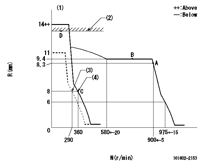
N:Pump speed
R:Rack position (mm)
(1)Target notch: K
(2)RACK LIMIT
(3)Set idle sub-spring
(4)Main spring setting
----------
K=5
----------
----------
K=5
----------
Speed control lever angle
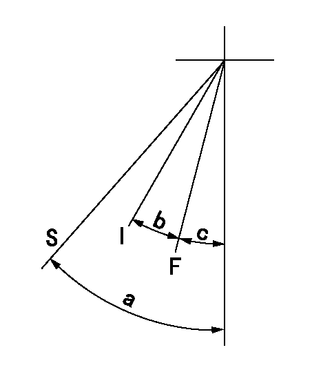
F:Full speed
I:Idle
S:Stop
----------
----------
a=32deg+-3deg b=(14deg)+-5deg c=(5deg)+-5deg
----------
----------
a=32deg+-3deg b=(14deg)+-5deg c=(5deg)+-5deg
Timing setting

(1)Pump vertical direction
(2)Position of gear's standard threaded hole at No 1 cylinder's beginning of injection
(3)-
(4)-
----------
----------
a=(70deg)
----------
----------
a=(70deg)
Information:
Determine the fuel rail pressure and the injector test engine speed (where the peak pressure was selected). Typically, pressure will start building after 2 to 5 seconds and then there should be sampling for 5 more seconds. Illustration 7 shows an example of selecting the peak pressure and corresponding speed.
Calculate the speed change of the injector test as follows:Injector test speed change equals injector test engine speed minus pump test engine speed.
Determine injector pressure correction using the injector test speed change and Table 5. This will correct for pressure change as speed changes.
Table 5
Injector Pressure Correction Based on Speed Change
Engine speed change (rpm) 0-5 6-10 11-15 16-20 21-25 26-30 31-35
Six-cylinder pressure correction 283 kPa (41 psi) 896 kPa (130 psi) 1455 kPa (211 psi) 2013 kPa (292 psi) 2572 kPa (373 psi) 3130 kPa (454 psi) 3689 kPa (535 psi)
Four-cylinder pressure correction 159 kPa (23 psi) 510 kPa (74 psi) 834 kPa (121 psi) 1151 kPa (167 psi) 1469 kPa (213 psi) 1793 kPa (260 psi) 2110 kPa (306 psi)
If the injector test engine speed is lower than pump test engine speed, then correct the injector pressure by adding the correction as follows:Injector corrected pressure equals injector test pressure plus injector pressure correction.
If the injector test engine speed is higher than pump test engine speed (as can happen when a battery booster is used), then correct the injector test pressure by subtracting the pressure correction as follows:Injector corrected pressure equals injector test pressure minus injector pressure correction.
Calculate injector leakage ratio as follows:Injector leakage ratio equals injector corrected pressure divided by pump test rail pressure.If the Injector leakage ratio is less than 0.85, the injector must be replaced, if the injector leakage is greater than 0.85 the injector is within the required parameters.Remove the fuel line. Replace the cap on the fuel manifold (rail) and injector.
Proceed to the next injector to be checked. Repeat Step 1 through Step 8 for the remaining electronic unit injectors to be tested.
Remove components of 362-9754 Test Kit from the engine. Replace any fuel injection lines that were removed during the procedures. Refer to Disassembly and Assembly, Fuel Injection Lines - Install for the correct procedure.
Reconnect the electronic unit injector harness connectors.Test Kit Data Sheet
Table 6
Fuel Injection Pump Tests Pump Test Rail Pressure Pump Test Engine Speed Minimum Cranking Pressure (MCP) Service
From Pump Test Datalog From Pump
Have questions with 101602-2153?
Group cross 101602-2153 ZEXEL
Hino
101602-2153
9 400 614 754
220202013A
INJECTION-PUMP ASSEMBLY
W06D
W06D