Information injection-pump assembly
ZEXEL
101602-2090
1016022090
HINO
220201164A
220201164a

Rating:
Cross reference number
ZEXEL
101602-2090
1016022090
HINO
220201164A
220201164a
Zexel num
Bosch num
Firm num
Name
Calibration Data:
Adjustment conditions
Test oil
1404 Test oil ISO4113 or {SAEJ967d}
1404 Test oil ISO4113 or {SAEJ967d}
Test oil temperature
degC
40
40
45
Nozzle and nozzle holder
105780-8140
Bosch type code
EF8511/9A
Nozzle
105780-0000
Bosch type code
DN12SD12T
Nozzle holder
105780-2080
Bosch type code
EF8511/9
Opening pressure
MPa
17.2
Opening pressure
kgf/cm2
175
Injection pipe
Outer diameter - inner diameter - length (mm) mm 6-2-600
Outer diameter - inner diameter - length (mm) mm 6-2-600
Overflow valve
134424-0620
Overflow valve opening pressure
kPa
162
147
177
Overflow valve opening pressure
kgf/cm2
1.65
1.5
1.8
Tester oil delivery pressure
kPa
157
157
157
Tester oil delivery pressure
kgf/cm2
1.6
1.6
1.6
Direction of rotation (viewed from drive side)
Right R
Right R
Injection timing adjustment
Direction of rotation (viewed from drive side)
Right R
Right R
Injection order
1-4-2-6-
3-5
Pre-stroke
mm
4.85
4.8
4.9
Beginning of injection position
Drive side NO.1
Drive side NO.1
Difference between angles 1
Cal 1-4 deg. 60 59.5 60.5
Cal 1-4 deg. 60 59.5 60.5
Difference between angles 2
Cyl.1-2 deg. 120 119.5 120.5
Cyl.1-2 deg. 120 119.5 120.5
Difference between angles 3
Cal 1-6 deg. 180 179.5 180.5
Cal 1-6 deg. 180 179.5 180.5
Difference between angles 4
Cal 1-3 deg. 240 239.5 240.5
Cal 1-3 deg. 240 239.5 240.5
Difference between angles 5
Cal 1-5 deg. 300 299.5 300.5
Cal 1-5 deg. 300 299.5 300.5
Injection quantity adjustment
Adjusting point
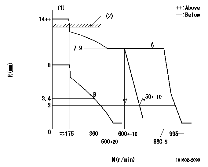
A
Rack position
7.9
Pump speed
r/min
700
700
700
Average injection quantity
mm3/st.
80.5
78.9
82.1
Max. variation between cylinders
%
0
-2
2
Basic
*
Fixing the lever
*
Injection quantity adjustment_02
Adjusting point
B
Rack position
4.3+-0.5
Pump speed
r/min
360
360
360
Average injection quantity
mm3/st.
9.5
8
11
Max. variation between cylinders
%
0
-15
15
Fixing the rack
*
Remarks
Adjust only variation between cylinders; adjust governor according to governor specifications.
Adjust only variation between cylinders; adjust governor according to governor specifications.
Test data Ex:
Governor adjustment
N:Pump speed
R:Rack position (mm)
(1)Target notch: K
(2)RACK LIMIT: RAL
----------
K=10 RAL=14+0.2mm
----------
----------
K=10 RAL=14+0.2mm
----------
Speed control lever angle
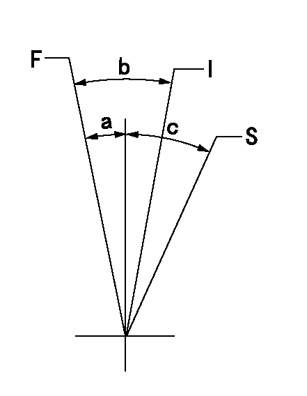
F:Full speed
I:Idle
S:Stop
----------
----------
a=0deg+-5deg b=25deg+-5deg c=32deg+-3deg
----------
----------
a=0deg+-5deg b=25deg+-5deg c=32deg+-3deg
Stop lever angle

N:Pump normal
S:Stop the pump.
----------
----------
a=27deg+-5deg b=53deg+-5deg
----------
----------
a=27deg+-5deg b=53deg+-5deg
Timing setting

(1)Pump vertical direction
(2)Coupling's key groove position at No 1 cylinder's beginning of injection
(3)-
(4)-
----------
----------
a=(60deg)
----------
----------
a=(60deg)
Information:
Illustration 2 g01178323
Proper Installation of Plug
Illustration 3 g01178325
DT Type sealing plugThe 8T-8729 Connector Pin (2) and the 8T-8730 Connector Socket (1) is designed to accept only one 16/18 AWG wire. Do not insert multiple wires of a smaller wire size. An incorrect method would be using two 24 AWG wires. The 9W-0852 Connector Pin and the 9W-0844 Connector Socket is designed to accept only one 14 AWG wire. Do not insert multiple wires of a smaller wire size. An example of an incorrect method is the use of two 20 AWG wires.
CHECK THE CONNECTORS.
Ensure that the connector is properly locked. Also, ensure that the two halves of the connector can not be pulled apart.
Verify that the latch tab of the connector is properly latched. Verify that the latch tab of the connector is fully latched. Expected Result: The connector will securely lock. The connector and the locking mechanism are without cracks or breaks.Results:OK - The connector will securely lock. The connector and the locking mechanism are without cracks or breaks. Proceed to test Step 2. NOT OK - A problem exists with the connector.Repair: Repair the connector or replace the connector, as required.STOP.
CHECK THE ALLEN HEAD SCREW ON THE HARNESS CONNECTOR OF THE ECM.
Ensure that the connector bolt is properly tightened. Be careful not to tighten the bolt too much. The bolt may break.
Do not exceed 6.0 N m (53.0 lb in) of torque on the connector bolt of the harness when the connector is being installed on the ECM. Expected Result: The harness connector is secure and the connector bolt of the ECM is properly torqued.Results:OK - The harness connector is secure and the connector is properly torqued. Proceed to test Step 3.NOT OK - A problem exists with the connector.Repair: Secure the harness connector of the ECM. Ensure that the connector bolt is properly torqued.STOP.
PERFORM A PULL TEST ON EACH CONNECTOR CONTACT.
Each connector contact should withstand 45 N (10 lb) of pull. Each wire should remain in the connector body. This test checks whether the wire was properly crimped in the contact and whether the contact was properly inserted into the connector.
The DT connectors use an orange wedge to lock the terminals in place.
Check in order to ensure that the orange wedge is not missing and that the orange wedge is installed properly on the DT connectors.Note: A Crimp Tool should ALWAYS be used in order to crimp wires on connector contacts. Do not solder the terminals. Use the proper Crimp Tool.Expected Result: Each connector contact should withstand 45 N (10 lb) of pull. Each wire remains in the connector body. Results:OK - Each connector contact withstands 45 N (10 lb) of pull. Each wire remains in the connector body. Proceed to test Step 4.NOT OK - A problem exists with the connector.Repair: Repair the wiring or replace the connector contact.STOP.
CHECK THE WIRES FOR NICKS OR ABRASIONS IN THE INSULATION.
Carefully inspect each wire for signs of abrasion, nicks, or cuts. The following areas are locations