Information injection-pump assembly
ZEXEL
101602-2080
1016022080
HINO
220201940A
220201940a

Rating:
Cross reference number
ZEXEL
101602-2080
1016022080
HINO
220201940A
220201940a
Zexel num
Bosch num
Firm num
Name
Calibration Data:
Adjustment conditions
Test oil
1404 Test oil ISO4113 or {SAEJ967d}
1404 Test oil ISO4113 or {SAEJ967d}
Test oil temperature
degC
40
40
45
Nozzle and nozzle holder
105780-8140
Bosch type code
EF8511/9A
Nozzle
105780-0000
Bosch type code
DN12SD12T
Nozzle holder
105780-2080
Bosch type code
EF8511/9
Opening pressure
MPa
17.2
Opening pressure
kgf/cm2
175
Injection pipe
Outer diameter - inner diameter - length (mm) mm 6-2-600
Outer diameter - inner diameter - length (mm) mm 6-2-600
Overflow valve
134424-0620
Overflow valve opening pressure
kPa
162
147
177
Overflow valve opening pressure
kgf/cm2
1.65
1.5
1.8
Tester oil delivery pressure
kPa
157
157
157
Tester oil delivery pressure
kgf/cm2
1.6
1.6
1.6
Direction of rotation (viewed from drive side)
Right R
Right R
Injection timing adjustment
Direction of rotation (viewed from drive side)
Right R
Right R
Injection order
1-4-2-6-
3-5
Pre-stroke
mm
4.85
4.8
4.9
Beginning of injection position
Drive side NO.1
Drive side NO.1
Difference between angles 1
Cal 1-4 deg. 60 59.5 60.5
Cal 1-4 deg. 60 59.5 60.5
Difference between angles 2
Cyl.1-2 deg. 120 119.5 120.5
Cyl.1-2 deg. 120 119.5 120.5
Difference between angles 3
Cal 1-6 deg. 180 179.5 180.5
Cal 1-6 deg. 180 179.5 180.5
Difference between angles 4
Cal 1-3 deg. 240 239.5 240.5
Cal 1-3 deg. 240 239.5 240.5
Difference between angles 5
Cal 1-5 deg. 300 299.5 300.5
Cal 1-5 deg. 300 299.5 300.5
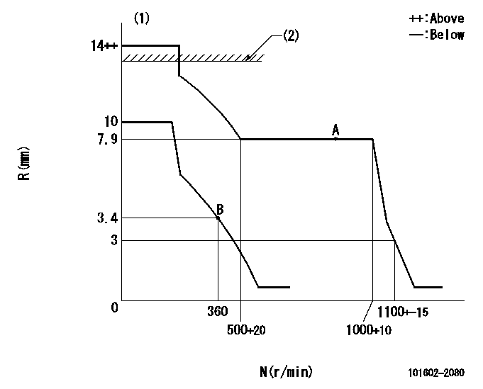
Injection quantity adjustment
Adjusting point
A
Rack position
7.9
Pump speed
r/min
700
700
700
Average injection quantity
mm3/st.
80.5
78.9
82.1
Max. variation between cylinders
%
0
-2
2
Basic
*
Fixing the lever
*
Injection quantity adjustment_02
Adjusting point
B
Rack position
4.2+-0.5
Pump speed
r/min
360
360
360
Average injection quantity
mm3/st.
9.5
8
11
Max. variation between cylinders
%
0
-15
15
Fixing the rack
*
Remarks
Adjust only variation between cylinders; adjust governor according to governor specifications.
Adjust only variation between cylinders; adjust governor according to governor specifications.
Test data Ex:
Governor adjustment
N:Pump speed
R:Rack position (mm)
(1)Target notch: K
(2)RACK LIMIT: RAL
----------
K=8 RAL=14+0.2mm
----------
----------
K=8 RAL=14+0.2mm
----------
Speed control lever angle

F:Full speed
I:Idle
(1)Stopper bolt setting
----------
----------
a=5.5deg+-5deg b=28deg+-5deg
----------
----------
a=5.5deg+-5deg b=28deg+-5deg
Stop lever angle

N:Pump normal
S:Stop the pump.
----------
----------
a=27deg+-5deg b=53deg+-5deg
----------
----------
a=27deg+-5deg b=53deg+-5deg
Timing setting

(1)Pump vertical direction
(2)Coupling's key groove position at No 1 cylinder's beginning of injection
(3)-
(4)-
----------
----------
a=(60deg)
----------
----------
a=(60deg)
Information:
Clean any machining debris that may be on the inside of the flywheel housing.Ensure that the debris guard is clean. A clean guard will ensure that no machining debris falls into the engine when the debris guard is removed.
Remove the debris guard from the inside of the flywheel housing.Install the Pipe Adapters and Sensors
Use 12 5P-2424 Bolts and 118-0275 Washers in order to install wheel (1) onto the cam gear.
Illustration 24 g01323683
(K) Installation guide for the pipe adapters
Illustration 25 g01323672
(1) 284-8910 Wheel
Install the installation guide for the pipe adapters.The installation guide must be installed on the evenly spaced teeth of wheel (1). Refer to Illustration 25.
Illustration 26 g01323669
(2) Fabricated pipe adapters
Install the top and the bottom pipe adapters (2) that were fabricated from the design in Illustration 6.
Use 7M-7456 Bearing Mount Compound to coat the outside of pipe adapter (2) .
Ensure that the adapter is properly aligned with the machined hole.
Illustration 27 g01323703
(L) Bushing driver (2) Pipe adapter
Illustration 28 g01323665
Pipe adapter (2) in contact with installation guide (K)
Use bushing driver (L) to install pipe adapters (2) .Continue installing the pipe adapters until the adapters contact the installation guide. The guide will not wiggle when the adapters are properly installed. Refer to Illustrations 27 and 28.
Remove the installation guide.
Illustration 29 g01324920
Correct alignment of the center pole of the speed sensor (3) Center pole of the speed sensor
Inspect the hole in pipe adapters (2) .The tooth of wheel (1) must be in the center of the hole in the pipe adapter. In order to ensure that the speed sensor will operate correctly, the center of the speed sensor must align with a tooth on wheel (1). Refer to Illustration 29 for an example of the correct alignment.
Illustration 30 g01323661
183-8597 Speed Sensor Gp
Illustration 31 g01323666
Speed sensors (5) Primary speed sensor (6) Secondary speed sensor
Install 3K-0360 O-Ring Seals with primary speed sensor (5) and secondary speed sensor (6) . 183-8597 Speed Sensor Gp Torque ... 37 4 N m (27 3 lb ft) Clearance between tip of sensor and the wheel ... 0.750 mm to 2.000 mm (0.0295 inch to 0.0787 inch)Note: Note the position of extra tooth (7) in relation to primary speed sensor (5) .Note: The 284-8909 Camshaft Gear may need repositioned in order to adjust the position of wheel (1).
Illustration 32 g01323706
Typical example of wheel (1) in standard rotation (7) Extra tooth
Illustration 33 g01323668
Typical example of wheel (1) in reverse rotation
Adjust the 284-8910 Wheel .
Align the first tooth after extra tooth (7) with the center of the primary speed sensor.Refer to Illustration 32.
Torque the bolts to 120 N m (89 lb ft).
Recheck the alignment of the first tooth after extra tooth (7) and the primary speed sensor.
Install the 240-9736 Cylinder Block Cover Gp .
Use 0S-1594 Bolts and 3V-3308 Hard Washers in order to install the two 4B-3140 Covers and the 1W-1960 Gaskets onto the front housing of the engine.
Use 3B-1915 Bolts and 3V-3308 Hard Washers in order to install the 7E-5420 Cover and