Information injection-pump assembly
ZEXEL
101602-1550
1016021550

Rating:
Cross reference number
ZEXEL
101602-1550
1016021550
Zexel num
Bosch num
Firm num
Name
101602-1550
INJECTION-PUMP ASSEMBLY
14BE PE6A PE
14BE PE6A PE
Calibration Data:
Adjustment conditions
Test oil
1404 Test oil ISO4113 or {SAEJ967d}
1404 Test oil ISO4113 or {SAEJ967d}
Test oil temperature
degC
40
40
45
Nozzle and nozzle holder
105780-8140
Bosch type code
EF8511/9A
Nozzle
105780-0000
Bosch type code
DN12SD12T
Nozzle holder
105780-2080
Bosch type code
EF8511/9
Opening pressure
MPa
17.2
Opening pressure
kgf/cm2
175
Injection pipe
Outer diameter - inner diameter - length (mm) mm 6-2-600
Outer diameter - inner diameter - length (mm) mm 6-2-600
Overflow valve
131424-5520
Overflow valve opening pressure
kPa
255
221
289
Overflow valve opening pressure
kgf/cm2
2.6
2.25
2.95
Tester oil delivery pressure
kPa
157
157
157
Tester oil delivery pressure
kgf/cm2
1.6
1.6
1.6
Direction of rotation (viewed from drive side)
Right R
Right R
Injection timing adjustment
Direction of rotation (viewed from drive side)
Right R
Right R
Injection order
1-5-3-6-
2-4
Pre-stroke
mm
3.5
3.45
3.55
Beginning of injection position
Drive side NO.1
Drive side NO.1
Difference between angles 1
Cal 1-5 deg. 60 59.5 60.5
Cal 1-5 deg. 60 59.5 60.5
Difference between angles 2
Cal 1-3 deg. 120 119.5 120.5
Cal 1-3 deg. 120 119.5 120.5
Difference between angles 3
Cal 1-6 deg. 180 179.5 180.5
Cal 1-6 deg. 180 179.5 180.5
Difference between angles 4
Cyl.1-2 deg. 240 239.5 240.5
Cyl.1-2 deg. 240 239.5 240.5
Difference between angles 5
Cal 1-4 deg. 300 299.5 300.5
Cal 1-4 deg. 300 299.5 300.5
Injection quantity adjustment
Adjusting point
A
Rack position
9.8
Pump speed
r/min
800
800
800
Average injection quantity
mm3/st.
71.5
70.5
72.5
Max. variation between cylinders
%
0
-2.5
2.5
Basic
*
Fixing the lever
*
Injection quantity adjustment_02
Adjusting point
-
Rack position
7.4+-0.5
Pump speed
r/min
450
450
450
Average injection quantity
mm3/st.
8
6.7
9.3
Max. variation between cylinders
%
0
-14
14
Fixing the rack
*
Remarks
Adjust only variation between cylinders; adjust governor according to governor specifications.
Adjust only variation between cylinders; adjust governor according to governor specifications.
Injection quantity adjustment_03
Adjusting point
D
Rack position
-
Pump speed
r/min
100
100
100
Average injection quantity
mm3/st.
65
65
70
Fixing the lever
*
Rack limit
*
Test data Ex:
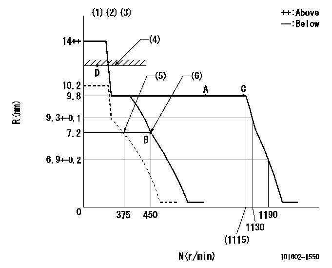
Governor adjustment

N:Pump speed
R:Rack position (mm)
(1)Target notch: K
(2)Tolerance for racks not indicated: +-0.05mm.
(3)Supplied with torque spring not set.
(4)RACK LIMIT
(5)Set idle sub-spring
(6)Main spring setting
----------
K=9
----------
----------
K=9
----------
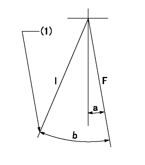
Speed control lever angle

F:Full speed
I:Idle
(1)Stopper bolt setting
----------
----------
a=5deg+-5deg b=24deg+-5deg
----------
----------
a=5deg+-5deg b=24deg+-5deg
Stop lever angle

N:Pump normal
S:Stop the pump.
----------
----------
a=27deg+-5deg b=53deg+-5deg
----------
----------
a=27deg+-5deg b=53deg+-5deg
Timing setting

(1)Pump vertical direction
(2)Position of gear mark '3' at No 1 cylinder's beginning of injection
(3)B.T.D.C.: aa
(4)-
----------
aa=12.5deg
----------
a=(130deg)
----------
aa=12.5deg
----------
a=(130deg)
Information:
Illustration 2 g01180699
Pour point of fuel mixturesIn order to calculate the amount of lighter fuel that is required to be blended with the heavier fuel, perform the following steps:
Obtain the specification for the cloud point or the pour point of both fuels from your fuel supplier.
Locate the cloud point or the pour point of the heavier fuel on the left side of the table. Mark the point on the table.
Locate the cloud point or the pour point of the lighter fuel on the right side of the table. Mark the point on the table.
Draw a line between the two points that were established. Label this line "A".
Determine the lowest outside temperature for machine operation. Find this point on the left side of the table. Mark this point. Draw a horizontal line from this point. Stop the line at the intersection of line "A". Label this new line "C".
Line "C" and line "A" intersect. Mark this point. Draw a vertical line from this point. Stop the line at the bottom of the table. Label this line "B". The point at the bottom of line "B" reveals the percentage of lighter fuel that is required to modify the cloud point or the pour point.The above example shows that the blending will require a thirty percent mixture of lighter fuel.Additives are a good method to use in order to lower the pour point of a fuel. These additives are known by the following names: pour point depressants, cold flow improvers and wax modifiers. When the additives are used in a low concentration, the fuel will flow through pumps, lines, and hoses.Note: These additives must be thoroughly mixed into the fuel at temperatures that are above the cloud point. The fuel supplier should be consulted in order to blend the fuel with the additives. The blended fuel can be delivered to your fuel tanks.Moisture Content
Problems with fuel filters can occur at any time. The cause of the problem can be water in the fuel or moisture in the fuel. At low temperatures, moisture causes special problems. There are three types of moisture in fuel: dissolved moisture (moisture in solution), free and dispersed moisture in the fuel and free and settled at the bottom of the tank.Most diesel fuels have some dissolved moisture. Just as the moisture in air, the fuel can only contain a specific maximum amount of moisture at any one temperature. The amount of moisture decreases as the temperature is lowered. For example, a fuel could contain 100 ppm (0.010 percent) of water in solution at 18°C (65°F). This same fuel can possibly hold only 30 ppm (0.003 percent) at 4°C (40°F).After the fuel has absorbed the maximum possible amount of water, the additional water will be free and dispersed. Free and dispersed moisture is fine droplets of water that is suspended in the fuel. Since the water is heavier than the fuel, the water will slowly become free and settled at the bottom of the tank. In the above
Have questions with 101602-1550?
Group cross 101602-1550 ZEXEL
Mitsubishi
Mitsubishi
Mitsubishi
101602-1550
INJECTION-PUMP ASSEMBLY