Information injection-pump assembly
BOSCH
9 400 614 742
9400614742
ZEXEL
101602-1471
1016021471
MITSUBISHI
ME078402
me078402
Rating:
Include in #2:
105856-4470
as _
Cross reference number
BOSCH
9 400 614 742
9400614742
ZEXEL
101602-1471
1016021471
MITSUBISHI
ME078402
me078402
Zexel num
Bosch num
Firm num
Name
101602-1471
9 400 614 742
ME078402 MITSUBISHI
INJECTION-PUMP ASSEMBLY
6D16T K
6D16T K
Calibration Data:
Adjustment conditions
Test oil
1404 Test oil ISO4113 or {SAEJ967d}
1404 Test oil ISO4113 or {SAEJ967d}
Test oil temperature
degC
40
40
45
Nozzle and nozzle holder
105780-8140
Bosch type code
EF8511/9A
Nozzle
105780-0000
Bosch type code
DN12SD12T
Nozzle holder
105780-2080
Bosch type code
EF8511/9
Opening pressure
MPa
17.2
Opening pressure
kgf/cm2
175
Injection pipe
Outer diameter - inner diameter - length (mm) mm 6-2-600
Outer diameter - inner diameter - length (mm) mm 6-2-600
Overflow valve
131424-5520
Overflow valve opening pressure
kPa
255
221
289
Overflow valve opening pressure
kgf/cm2
2.6
2.25
2.95
Tester oil delivery pressure
kPa
157
157
157
Tester oil delivery pressure
kgf/cm2
1.6
1.6
1.6
Direction of rotation (viewed from drive side)
Left L
Left L
Injection timing adjustment
Direction of rotation (viewed from drive side)
Left L
Left L
Injection order
1-5-3-6-
2-4
Pre-stroke
mm
4.5
4.45
4.55
Beginning of injection position
Governor side NO.1
Governor side NO.1
Difference between angles 1
Cal 1-5 deg. 60 59.5 60.5
Cal 1-5 deg. 60 59.5 60.5
Difference between angles 2
Cal 1-3 deg. 120 119.5 120.5
Cal 1-3 deg. 120 119.5 120.5
Difference between angles 3
Cal 1-6 deg. 180 179.5 180.5
Cal 1-6 deg. 180 179.5 180.5
Difference between angles 4
Cyl.1-2 deg. 240 239.5 240.5
Cyl.1-2 deg. 240 239.5 240.5
Difference between angles 5
Cal 1-4 deg. 300 299.5 300.5
Cal 1-4 deg. 300 299.5 300.5
Injection quantity adjustment
Adjusting point
A
Rack position
9.6
Pump speed
r/min
750
750
750
Average injection quantity
mm3/st.
122
118.5
125.5
Max. variation between cylinders
%
0
-3
3
Basic
*
Fixing the lever
*
Injection quantity adjustment_02
Adjusting point
-
Rack position
6.4+-0.5
Pump speed
r/min
350
350
350
Average injection quantity
mm3/st.
10.6
9.1
12.1
Max. variation between cylinders
%
0
-15
15
Fixing the rack
*
Remarks
Adjust only variation between cylinders; adjust governor according to governor specifications.
Adjust only variation between cylinders; adjust governor according to governor specifications.
Test data Ex:
Governor adjustment
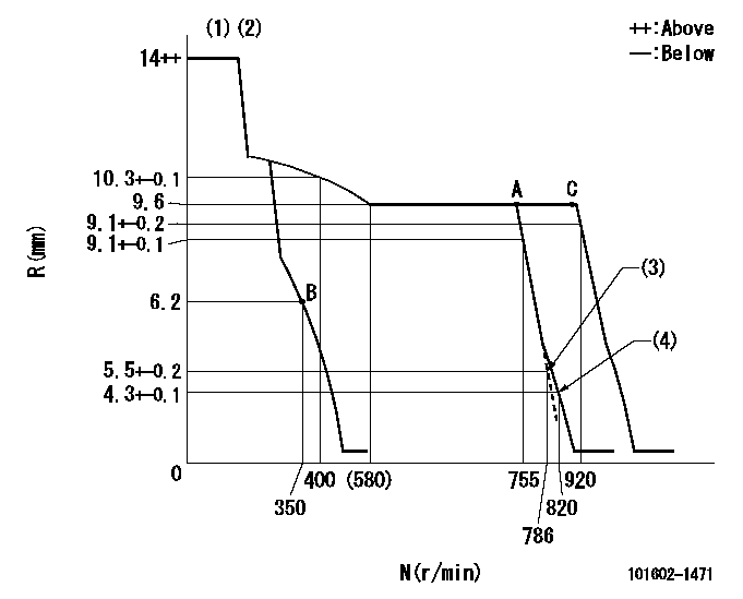
N:Pump speed
R:Rack position (mm)
(1)Target notch: K
(2)Tolerance for racks not indicated: +-0.05mm.
(3)Main spring setting
(4)Set idle sub-spring
----------
K=13
----------
----------
K=13
----------
Speed control lever angle
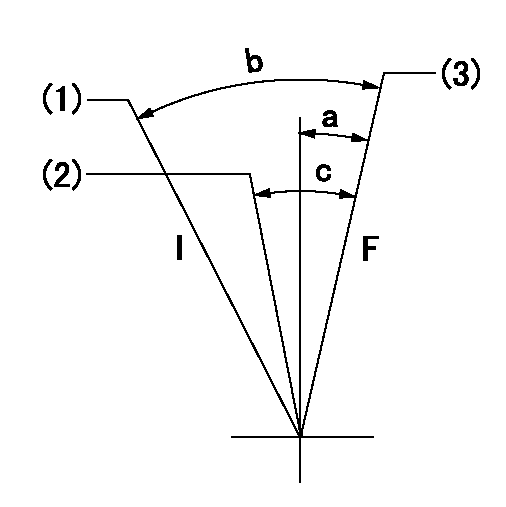
F:Full speed
I:Idle
(1)Stopper bolt setting
(2)Pump speed = aa
(3)Pump speed = bb (at delivery)
----------
aa=755r/min bb=920r/min
----------
a=0deg+-5deg b=24deg+-5deg c=6deg+-5deg
----------
aa=755r/min bb=920r/min
----------
a=0deg+-5deg b=24deg+-5deg c=6deg+-5deg
Stop lever angle

N:Pump normal
S:Stop the pump.
----------
----------
a=26deg+-5deg b=53deg+-5deg
----------
----------
a=26deg+-5deg b=53deg+-5deg
Timing setting

(1)Pump vertical direction
(2)Position of coupling's tooth at No 1 cylinder's beginning of injection
(3)B.T.D.C.: aa
(4)-
----------
aa=10deg
----------
a=(1deg)
----------
aa=10deg
----------
a=(1deg)
Information:
Connect cable (2) to the RS-232 serial port of PC (1) .
Connect cable (2) to communication adapter (3) .
Connect cable (4) to communication adapter (3) .
Connect cable (4) to the service tool connector on the engine mounted CIP.
Turn the engine control switch to the LOCAL position or to the REMOTE position. Turn the fuel control switch to the FUEL OFF position. The engine should be OFF.If Cat ET and the communication adapter do not communicate with the ECM, refer to Troubleshooting, RENR5910, "Electronic Service Tool Will Not Communicate With ECM".Troubleshooting
Refer to Troubleshooting, RENR5084 for more information on the following components.
Sensor faults
Injector faults
Response checks for the throttle input
Shutdown input response checksRequirements for the Electrical System
When you route the wiring, avoid acute bends and sharp edges. To protect the wiring harnesses, route the harnesses through a metal conduit. Use a rigid conduit or a use flexible conduit. A liquid tight conduit is recommended. Use proper support and alignment in order to avoid strain on the conduit.Electronic Service Tools
Caterpillar Electronic Service Tools are designed to help the service technician:
Obtain data.
Diagnose problems.
Read parameters.
Program parameters.
Calibrate sensors.The tools that are listed in Table 12 are required in order to enable a service technician to perform the electrical installation procedures and the initial start-up.Note: Other tools that are needed for measuring operating parameters such as pressure and temperature are not listed in Table 12.
Table 12
Service Tools
Pt. No. Description Functions
N/A Personal Computer (PC) This PC configuration is recommended:
Intel Pentium II 333 mHz processor
64 megabyte of RAM
4.3 GB hard drive
Drive for floppy disks (3.5 inch with 1.44 MB)
14X speed CD-ROM drive
VGA monitor or display
RS-232 port with 16550AF UART
Windows NT 4.0 (1)
Windows 95 (1)
Windows 98 (1)
Mouse
N/A Personal Computer (PC) This PC configuration has the minimum requirements:
IBM PC compatible 100 MHz processor
32 megabyte of RAM
10 MB of available hard drive space
CD-ROM drive
Drive for floppy disks (3.5 inch with 1.44 MB)
Windows NT 4.0 (1)
Windows 95 (1)
Windows 98 (1)
RS-232 port with 16550AF UART
VGA monitor or display
Mouse
"JERD2124" Software Single user license for Caterpillar Electronic Technician (Cat ET)
Use the most recent version of this software.
"JERD2129" Software Data subscription for all engines
171-4401 Communication Adapter II (1) The communication adapter is connected between the PC (ET) and the ECM.
196-0055 Serial Cable As This cable connects the PC to the 171-4401 Communication Adapter II .
7X-1414 Data Link Cable As This cable connects the service tool connector on the engine mounted junction box to the 139-4166 Adapter Cable As .
8T-8726 Adapter Cable As This breakout t is for use between the jacks and the plugs of the sensors.
151-6320 Wire Removal Tool This tool is used for the removal of pins and sockets from Deutsch connectors and AMP connectors.
1U-5804 Crimp Tool This tool is used for work with
Have questions with 101602-1471?
Group cross 101602-1471 ZEXEL
Mitsubishi
Mitsubishi
Mitsubishi
Mitsubishi
101602-1471
9 400 614 742
ME078402
INJECTION-PUMP ASSEMBLY
6D16T
6D16T