Information injection-pump assembly
ZEXEL
101602-1462
1016021462
Rating:
Service parts 101602-1462 INJECTION-PUMP ASSEMBLY:
1.
_

5.
AUTOM. ADVANCE MECHANIS
6.
COUPLING PLATE
8.
_
9.
_
11.
Nozzle and Holder
ME078365
12.
Open Pre:MPa(Kqf/cm2)
17.7{180}

15.
NOZZLE SET
Include in #1:
101602-1462
as INJECTION-PUMP ASSEMBLY
Include in #2:
105866-7201
as _
Cross reference number
ZEXEL
101602-1462
1016021462
Zexel num
Bosch num
Firm num
Name
101602-1462
INJECTION-PUMP ASSEMBLY
Calibration Data:
Adjustment conditions
Test oil
1404 Test oil ISO4113 or {SAEJ967d}
1404 Test oil ISO4113 or {SAEJ967d}
Test oil temperature
degC
40
40
45
Nozzle and nozzle holder
105780-8140
Bosch type code
EF8511/9A
Nozzle
105780-0000
Bosch type code
DN12SD12T
Nozzle holder
105780-2080
Bosch type code
EF8511/9
Opening pressure
MPa
17.2
Opening pressure
kgf/cm2
175
Injection pipe
Outer diameter - inner diameter - length (mm) mm 6-2-600
Outer diameter - inner diameter - length (mm) mm 6-2-600
Overflow valve
131424-5520
Overflow valve opening pressure
kPa
255
221
289
Overflow valve opening pressure
kgf/cm2
2.6
2.25
2.95
Tester oil delivery pressure
kPa
157
157
157
Tester oil delivery pressure
kgf/cm2
1.6
1.6
1.6
Direction of rotation (viewed from drive side)
Left L
Left L
Injection timing adjustment
Direction of rotation (viewed from drive side)
Left L
Left L
Injection order
1-5-3-6-
2-4
Pre-stroke
mm
4.5
4.45
4.55
Beginning of injection position
Governor side NO.1
Governor side NO.1
Difference between angles 1
Cal 1-5 deg. 60 59.5 60.5
Cal 1-5 deg. 60 59.5 60.5
Difference between angles 2
Cal 1-3 deg. 120 119.5 120.5
Cal 1-3 deg. 120 119.5 120.5
Difference between angles 3
Cal 1-6 deg. 180 179.5 180.5
Cal 1-6 deg. 180 179.5 180.5
Difference between angles 4
Cyl.1-2 deg. 240 239.5 240.5
Cyl.1-2 deg. 240 239.5 240.5
Difference between angles 5
Cal 1-4 deg. 300 299.5 300.5
Cal 1-4 deg. 300 299.5 300.5
Injection quantity adjustment
Adjusting point
A
Rack position
9.4
Pump speed
r/min
750
750
750
Average injection quantity
mm3/st.
118.5
115
122
Max. variation between cylinders
%
0
-3
3
Basic
*
Fixing the lever
*
Boost pressure
kPa
53.3
53.3
Boost pressure
mmHg
400
400
Injection quantity adjustment_02
Adjusting point
-
Rack position
6.4+-0.5
Pump speed
r/min
350
350
350
Average injection quantity
mm3/st.
10.6
9.1
12.1
Max. variation between cylinders
%
0
-15
15
Fixing the rack
*
Boost pressure
kPa
0
0
0
Boost pressure
mmHg
0
0
0
Remarks
Adjust only variation between cylinders; adjust governor according to governor specifications.
Adjust only variation between cylinders; adjust governor according to governor specifications.
Boost compensator adjustment
Pump speed
r/min
650
650
650
Rack position
R1-0.75
Boost pressure
kPa
28
25.3
30.7
Boost pressure
mmHg
210
190
230
Boost compensator adjustment_02
Pump speed
r/min
650
650
650
Rack position
R1(9.4)
Boost pressure
kPa
40
33.3
46.7
Boost pressure
mmHg
300
250
350
Test data Ex:
Governor adjustment
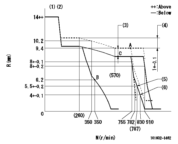
N:Pump speed
R:Rack position (mm)
(1)Target notch: K
(2)Tolerance for racks not indicated: +-0.05mm.
(3)Boost compensator stroke: BCL
(4)Rack difference between N = N1 and N = N2
(5)Main spring setting
(6)Set idle sub-spring
----------
K=15 BCL=0.75+-0.1mm N1=750r/min N2=230r/min
----------
----------
K=15 BCL=0.75+-0.1mm N1=750r/min N2=230r/min
----------
Speed control lever angle
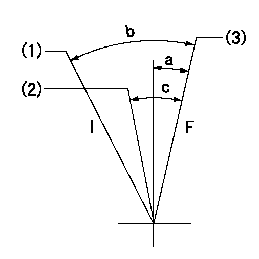
F:Full speed
I:Idle
(1)Stopper bolt setting
(2)Pump speed = aa
(3)Pump speed = bb
----------
aa=755r/min bb=910r/min
----------
a=(1deg)+-5deg b=(20deg)+-5deg c=(6deg)+-5deg
----------
aa=755r/min bb=910r/min
----------
a=(1deg)+-5deg b=(20deg)+-5deg c=(6deg)+-5deg
Stop lever angle
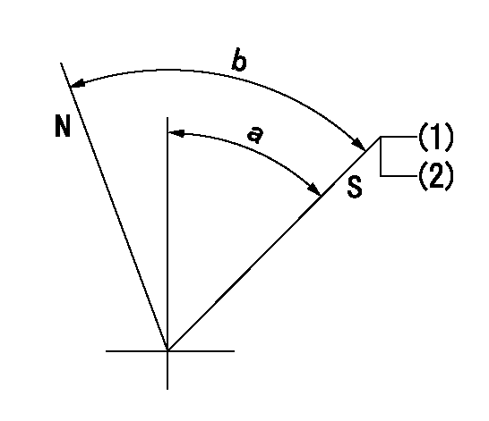
N:Pump normal
S:Stop the pump.
(1)Pump speed aa, rack position bb
(2)(Seal at delivery.)
----------
aa=0r/min bb=1-0.5mm
----------
a=35deg+-5deg b=(55deg)
----------
aa=0r/min bb=1-0.5mm
----------
a=35deg+-5deg b=(55deg)
Timing setting

(1)Pump vertical direction
(2)Position of coupling's tooth at No 1 cylinder's beginning of injection
(3)B.T.D.C.: aa
(4)-
----------
aa=12deg
----------
a=(0deg)
----------
aa=12deg
----------
a=(0deg)
Information:
Tools that are Required for Installation
Table 2
Required Tools
Tool Part Number Part Description Qty
B 9U-6862 Tapered Brush 1
9U-6863 Small Bore Brush 1
9U-7244 End Brush 1
9U-7237 Brush Extension 1
4C-5552 Large Bore Brush 1
C (1) 221-9778 Puller Stud 1
D (1) 9U-7258 Driver Cap 1
E 4C-9507 Retaining Compound -
( 1 ) Part of the 9U-6891 Injector Tool Group Removal Procedure
Keep all parts clean from contaminants.Contaminants may cause rapid wear and shortened component life.
Remove the electronic unit injector. Refer to Disassembly and Assembly, "Electronic Unit Injector - Remove".
Illustration 1 g01016237
Install the puller stud from Tooling (A) into unit injector sleeve (1) .
Install the following parts from Tooling (A) over the stud: bridge puller, thrust bearing, hard washer and nut.
Tighten the nut until unit injector sleeve (1) is pulled free of the cylinder head assembly.Installation Procedure
Use Tooling (B) to clean the bore in the cylinder head for the electronic unit injector sleeve.
Ensure that the electronic unit injector sleeve and the cylinder head bore are completely free of oil, dirt, and sealant debris.
Illustration 2 g01120522
Install new O-ring seals (2) on electronic unit injector sleeve (1) .Note: Do not apply Tooling (E) to the cylinder head surfaces. Apply Tooling (E) on the electronic unit injector sleeve only.
Apply Tooling (E) to the contact surface of electronic unit injector sleeve (1) on the surface that is marked "X".
Lubricate O-ring seals (2) with clean engine oil.
Illustration 3 g01076119
Install Tooling (C) into the threads of electronic unit injector sleeve (1) .
Position Tooling (C) and the electronic unit injector sleeve in the cylinder head. Use care not to damage the O-ring seal on the electronic unit injector sleeve.
Use Tooling (D) and a hammer to install electronic unit injector sleeve (1) in the cylinder head.
Ensure that the electronic unit injector sleeve is properly seated in the cylinder head. The Tooling will "RING" when the electronic unit injector sleeve is fully seated in the bore of the cylinder head.
Remove Tooling (D) and Tooling (C). Use a clean towel and remove excess Tooling (E) .
Install the electronic unit injector. Refer to Disassembly and Assembly, "Electronic Unit Injector - Install".
Fill the cooling system with coolant. Refer to Operation and Maintenance, "Refill Capacities" for the cooling system capacity.
Have questions with 101602-1462?
Group cross 101602-1462 ZEXEL
Mitsubishi
Mitsubishi
101602-1462
INJECTION-PUMP ASSEMBLY