Information injection-pump assembly
BOSCH
F 019 Z10 108
f019z10108
ZEXEL
101602-1461
1016021461

Rating:
Service parts 101602-1461 INJECTION-PUMP ASSEMBLY:
1.
_

5.
AUTOM. ADVANCE MECHANIS
6.
COUPLING PLATE
8.
_
9.
_
11.
Nozzle and Holder
ME078365
12.
Open Pre:MPa(Kqf/cm2)
17.7{180}

15.
NOZZLE SET
Include in #1:
101602-1461
as INJECTION-PUMP ASSEMBLY
Include in #2:
105866-7191
as _
Cross reference number
BOSCH
F 019 Z10 108
f019z10108
ZEXEL
101602-1461
1016021461
Zexel num
Bosch num
Firm num
Name
Calibration Data:
Adjustment conditions
Test oil
1404 Test oil ISO4113 or {SAEJ967d}
1404 Test oil ISO4113 or {SAEJ967d}
Test oil temperature
degC
40
40
45
Nozzle and nozzle holder
105780-8140
Bosch type code
EF8511/9A
Nozzle
105780-0000
Bosch type code
DN12SD12T
Nozzle holder
105780-2080
Bosch type code
EF8511/9
Opening pressure
MPa
17.2
Opening pressure
kgf/cm2
175
Injection pipe
Outer diameter - inner diameter - length (mm) mm 6-2-600
Outer diameter - inner diameter - length (mm) mm 6-2-600
Overflow valve
131424-5520
Overflow valve opening pressure
kPa
255
221
289
Overflow valve opening pressure
kgf/cm2
2.6
2.25
2.95
Tester oil delivery pressure
kPa
157
157
157
Tester oil delivery pressure
kgf/cm2
1.6
1.6
1.6
Direction of rotation (viewed from drive side)
Left L
Left L
Injection timing adjustment
Direction of rotation (viewed from drive side)
Left L
Left L
Injection order
1-5-3-6-
2-4
Pre-stroke
mm
4.5
4.45
4.55
Beginning of injection position
Governor side NO.1
Governor side NO.1
Difference between angles 1
Cal 1-5 deg. 60 59.5 60.5
Cal 1-5 deg. 60 59.5 60.5
Difference between angles 2
Cal 1-3 deg. 120 119.5 120.5
Cal 1-3 deg. 120 119.5 120.5
Difference between angles 3
Cal 1-6 deg. 180 179.5 180.5
Cal 1-6 deg. 180 179.5 180.5
Difference between angles 4
Cyl.1-2 deg. 240 239.5 240.5
Cyl.1-2 deg. 240 239.5 240.5
Difference between angles 5
Cal 1-4 deg. 300 299.5 300.5
Cal 1-4 deg. 300 299.5 300.5
Injection quantity adjustment
Adjusting point
A
Rack position
9.4
Pump speed
r/min
750
750
750
Average injection quantity
mm3/st.
118.5
115
122
Max. variation between cylinders
%
0
-3
3
Basic
*
Fixing the lever
*
Boost pressure
kPa
53.3
53.3
Boost pressure
mmHg
400
400
Injection quantity adjustment_02
Adjusting point
-
Rack position
6.4+-0.5
Pump speed
r/min
350
350
350
Average injection quantity
mm3/st.
10.6
9.1
12.1
Max. variation between cylinders
%
0
-15
15
Fixing the rack
*
Boost pressure
kPa
0
0
0
Boost pressure
mmHg
0
0
0
Remarks
Adjust only variation between cylinders; adjust governor according to governor specifications.
Adjust only variation between cylinders; adjust governor according to governor specifications.
Boost compensator adjustment
Pump speed
r/min
650
650
650
Rack position
R1-0.75
Boost pressure
kPa
28
25.3
30.7
Boost pressure
mmHg
210
190
230
Boost compensator adjustment_02
Pump speed
r/min
650
650
650
Rack position
R1(9.4)
Boost pressure
kPa
40
33.3
46.7
Boost pressure
mmHg
300
250
350
Test data Ex:
Governor adjustment
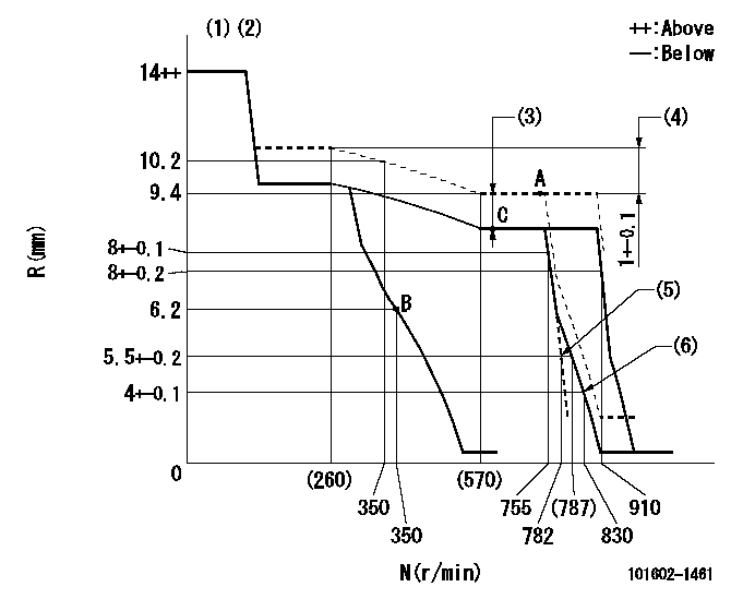
N:Pump speed
R:Rack position (mm)
(1)Target notch: K
(2)Tolerance for racks not indicated: +-0.05mm.
(3)Boost compensator stroke: BCL
(4)Rack difference between N = N1 and N = N2
(5)Main spring setting
(6)Set idle sub-spring
----------
K=15 BCL=0.75+-0.1mm N1=750r/min N2=230r/min
----------
----------
K=15 BCL=0.75+-0.1mm N1=750r/min N2=230r/min
----------
Speed control lever angle
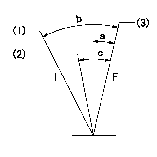
F:Full speed
I:Idle
(1)Stopper bolt setting
(2)Pump speed = aa
(3)Pump speed = bb
----------
aa=755r/min bb=910r/min
----------
a=(1deg)+-5deg b=(20deg)+-5deg c=(6deg)+-5deg
----------
aa=755r/min bb=910r/min
----------
a=(1deg)+-5deg b=(20deg)+-5deg c=(6deg)+-5deg
Stop lever angle
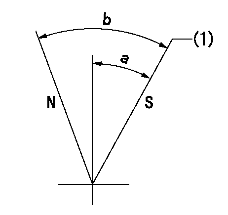
N:Pump normal
S:Stop the pump.
(1)Pump speed aa and rack position bb (to be sealed at delivery)
----------
aa=0r/min bb=1-0.5mm
----------
a=35deg+-5deg b=(55deg)
----------
aa=0r/min bb=1-0.5mm
----------
a=35deg+-5deg b=(55deg)
Timing setting

(1)Pump vertical direction
(2)Position of coupling's tooth at No 1 cylinder's beginning of injection
(3)B.T.D.C.: aa
(4)-
----------
aa=10deg
----------
a=(1deg)
----------
aa=10deg
----------
a=(1deg)
Information:
Remove the smaller hex nut (15.88 mm) (10) from the new 396-0380 Coupling along with ferrule (11) and ferrule (12). Orient the parts as shown in Illustration 3. Loosely install the parts onto the existing half of the 396-0380 Coupling on the engine. Refer to Illustration 4. Do not tighten the nut at this time.Note: Failure to orient the ferrules as shown in Illustration 3 will result in leakage and the need to replace the parts.
Illustration 5 g06054145
(14) 485-1630 Hose As
Push the quick-connect end of hose (14) onto the fuel pump drain line tube. An audible click should be heard and the fuel line should stay attached when gently pulled.
Illustration 6 g06054154
(14) 485-1630 Hose As
(15) 5P-9085 Clip
Place two new clips (15) onto hose (14) as shown in Illustration 6.
Illustration 7 g06054168
(14) 485-1630 Hose As
(16) 6V-8455 Bolt
(17) 8T-4121 Hard Washer
Illustration 8 g06054107
Lift the tube end of hose (14) and place the hose into the connector nut as shown in Illustration 8. Hand-tighten the nut, only.
Loosely secure the two clips with new bolts (16) and washers (17).
Illustration 9 g06054123
Mark the tube connector nut at the 6 o'clock position.
Illustration 10 g06054127
While holding the lower fitting stationary with another wrench and pushing the tube downward, tighten the nut one and one-quarter revolutions until the mark is at the 9 o'clock position. Refer to Illustrations 8,9, and 10.
Once the fitting is tightened, tighten bolts (16) securing the two clips (Illustration 7). Tighten the vertically mounted bolt first, then tighten the horizontally mounted bolt. Tighten each bolt to 25 2 N m (18.5 1.5 lb ft).
Reuse the existing hardware and reinstall the secondary fuel filter base. Tighten the bolts to 45 5 N m (33 4 lb ft). Hold the filter base vertical while tightening the bolts.
Illustration 11 g06054224
(18) Banjo bolt
(19) Spigot
(20) Front port
(21) Rear port
(22) 485-1627 Hose As
(25) 228-6046 Connector
(26) 228-7100 O-Ring Seal
Remove banjo bolt (18) and spigot (19). Retain one of the washers. Replace the banjo bolt with the new 8T-4191 Bolt and the retained washer. Tighten the bolt to 22 2 N m (16 1.5 lb ft).
Illustration 12 g06054327
Hose release orientation
(22) 485-1627 Hose As
Install hose (22) on the pump. It is important to note that the plastic release must be rotated so the flat is aligned with the body of the pump. Refer to Illustration 12.
Install connector (25) and O-Ring (26) at rear port (21). Tighten the connector to 30 2 N m (22 1.5 lb ft).
Install the new 228-7089 O-Ring Seal onto the connector. Then, install the other end of hose (22) to the connector. Holding the hose angle at approximately 5 degrees clockwise from vertical down, tighten the hose to 30 2 N m (22 1.5 lb ft).
Install a new 228-7100 O-Ring Seal onto the 8T-7487 Connector and install at front port (20). Tighten the connector to 30 2 N m (22 1.5 lb ft).
Install the new 228-7088 O-Ring Seal on the 8T-7487 Connector.
Illustration 13 g06054360
Connect braided hose (3) to