Information injection-pump assembly
ZEXEL
101602-1460
1016021460
Rating:
Service parts 101602-1460 INJECTION-PUMP ASSEMBLY:
1.
_

5.
AUTOM. ADVANCE MECHANIS
6.
COUPLING PLATE
8.
_
9.
_
11.
Nozzle and Holder
ME078365
12.
Open Pre:MPa(Kqf/cm2)
17.7{180}

15.
NOZZLE SET
Include in #1:
101602-1460
as INJECTION-PUMP ASSEMBLY
Include in #2:
105866-7121
as _
Cross reference number
ZEXEL
101602-1460
1016021460
Zexel num
Bosch num
Firm num
Name
101602-1460
INJECTION-PUMP ASSEMBLY
Calibration Data:
Adjustment conditions
Test oil
1404 Test oil ISO4113 or {SAEJ967d}
1404 Test oil ISO4113 or {SAEJ967d}
Test oil temperature
degC
40
40
45
Nozzle and nozzle holder
105780-8140
Bosch type code
EF8511/9A
Nozzle
105780-0000
Bosch type code
DN12SD12T
Nozzle holder
105780-2080
Bosch type code
EF8511/9
Opening pressure
MPa
17.2
Opening pressure
kgf/cm2
175
Injection pipe
Outer diameter - inner diameter - length (mm) mm 6-2-600
Outer diameter - inner diameter - length (mm) mm 6-2-600
Overflow valve
131424-5520
Overflow valve opening pressure
kPa
255
221
289
Overflow valve opening pressure
kgf/cm2
2.6
2.25
2.95
Tester oil delivery pressure
kPa
157
157
157
Tester oil delivery pressure
kgf/cm2
1.6
1.6
1.6
Direction of rotation (viewed from drive side)
Left L
Left L
Injection timing adjustment
Direction of rotation (viewed from drive side)
Left L
Left L
Injection order
1-5-3-6-
2-4
Pre-stroke
mm
4.5
4.45
4.55
Beginning of injection position
Governor side NO.1
Governor side NO.1
Difference between angles 1
Cal 1-5 deg. 60 59.5 60.5
Cal 1-5 deg. 60 59.5 60.5
Difference between angles 2
Cal 1-3 deg. 120 119.5 120.5
Cal 1-3 deg. 120 119.5 120.5
Difference between angles 3
Cal 1-6 deg. 180 179.5 180.5
Cal 1-6 deg. 180 179.5 180.5
Difference between angles 4
Cyl.1-2 deg. 240 239.5 240.5
Cyl.1-2 deg. 240 239.5 240.5
Difference between angles 5
Cal 1-4 deg. 300 299.5 300.5
Cal 1-4 deg. 300 299.5 300.5
Injection quantity adjustment
Adjusting point
A
Rack position
9.4
Pump speed
r/min
750
750
750
Average injection quantity
mm3/st.
118.5
115
122
Max. variation between cylinders
%
0
-3
3
Basic
*
Fixing the lever
*
Boost pressure
kPa
53.3
53.3
Boost pressure
mmHg
400
400
Injection quantity adjustment_02
Adjusting point
-
Rack position
6.4+-0.5
Pump speed
r/min
350
350
350
Average injection quantity
mm3/st.
10.6
9.1
12.1
Max. variation between cylinders
%
0
-15
15
Fixing the rack
*
Boost pressure
kPa
0
0
0
Boost pressure
mmHg
0
0
0
Remarks
Adjust only variation between cylinders; adjust governor according to governor specifications.
Adjust only variation between cylinders; adjust governor according to governor specifications.
Boost compensator adjustment
Pump speed
r/min
650
650
650
Rack position
R1-0.75
Boost pressure
kPa
28
25.3
30.7
Boost pressure
mmHg
210
190
230
Boost compensator adjustment_02
Pump speed
r/min
650
650
650
Rack position
R1(9.4)
Boost pressure
kPa
40
33.3
46.7
Boost pressure
mmHg
300
250
350
Test data Ex:
Governor adjustment
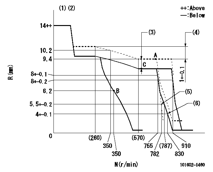
N:Pump speed
R:Rack position (mm)
(1)Target notch: K
(2)Tolerance for racks not indicated: +-0.05mm.
(3)Boost compensator stroke: BCL
(4)Rack difference between N = N1 and N = N2
(5)Main spring setting
(6)Set idle sub-spring
----------
K=15 BCL=0.75+-0.1mm N1=750r/min N2=230r/min
----------
----------
K=15 BCL=0.75+-0.1mm N1=750r/min N2=230r/min
----------
Speed control lever angle
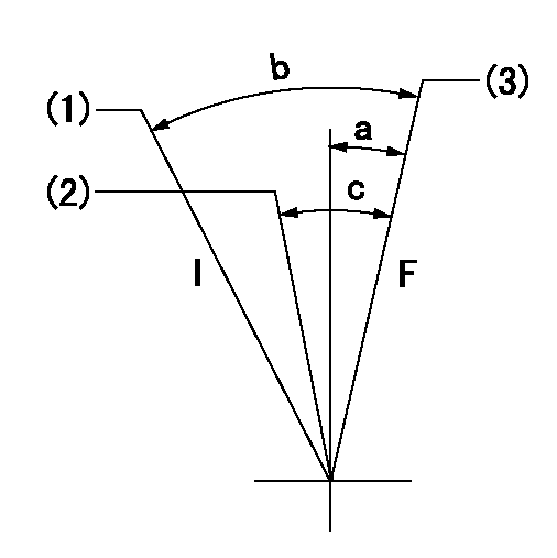
F:Full speed
I:Idle
(1)Stopper bolt setting
(2)Pump speed = aa
(3)Pump speed = bb
----------
aa=755r/min bb=910r/min
----------
a=(1deg)+-5deg b=(20deg)+-5deg c=(6deg)+-5deg
----------
aa=755r/min bb=910r/min
----------
a=(1deg)+-5deg b=(20deg)+-5deg c=(6deg)+-5deg
Stop lever angle
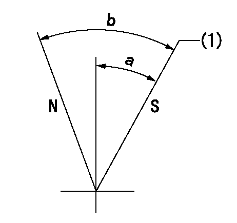
N:Pump normal
S:Stop the pump.
(1)Pump speed aa and rack position bb (to be sealed at delivery)
----------
aa=0r/min bb=1-0.5mm
----------
a=35deg+-5deg b=(55deg)
----------
aa=0r/min bb=1-0.5mm
----------
a=35deg+-5deg b=(55deg)
Timing setting

(1)Pump vertical direction
(2)Position of coupling's tooth at No 1 cylinder's beginning of injection
(3)B.T.D.C.: aa
(4)-
----------
aa=10deg
----------
a=(1deg)
----------
aa=10deg
----------
a=(1deg)
Information:
Do not use the same vacuum sampling pump for extracting oil samples that is used for extracting coolant samples.A small residue of either type sample may remain in the pump and may cause a false positive analysis for the sample being taken.Always use a separate pump for oil sampling and a separate pump for coolant sampling.Failure to do so may cause a false analysis which could lead to customer and dealer concerns.
New Systems, Refilled Systems, and Converted Systems
Perform an S O S coolant analysis (Level 2) at the following maintenance intervals.
Initial 500 service hours
Every Year or every 2000 hours, whichever comes firstPerform this analysis at the interval that occurs first for new systems, for refilled systems, or for converted systems that use Cat ELC (Extended Life Coolant) or use Cat DEAC (Diesel Engine Antifreeze/Coolant). This 500 hour check will also check for any residual cleaner that may have contaminated the system.Recommended Interval for S O S Services Coolant Sample
The following table contains the recommended sampling interval for all coolants that meet Cat EC-1 (Engine Coolant specification - 1). This is also the recommended sampling interval for all conventional heavy-duty coolant/antifreeze.The Level 2 Coolant Analysis should be performed if a problem is suspected or identified.
Table 1
Recommended Interval
Type of Coolant Level 1 Level 2
Cat DEAC
and Conventional Heavy-Duty Coolants Every 250 hours Yearly
Cat ELC
and Commercial EC-1 coolants Optional or every 500 hours Yearly or every 500 hours Note: Check the SCA (Supplemental Coolant Additive) of the conventional coolant at every oil change or at every 250 hours. Perform this check at the interval that occurs first.Refer to your machine OMM for recommendations specific to your machine.S O S Services Coolant Analysis (Level 1)
A coolant analysis (Level 1) is a test of the properties of the coolant.The following properties of the coolant are tested:
Glycol concentration for freeze protection and boil protection
Ability to protect from erosion and corrosion
pH
Conductivity
Visual analysis
Odor analysisThe results are reported, and appropriate recommendations are made.S O S Services Coolant Analysis (Level 2)
A coolant analysis ( Level 2) is a comprehensive chemical evaluation of the coolant. This analysis is also a check of the overall condition of the cooling system.The S O S coolant analysis ( Level 2) has the following features:
Full coolant analysis (Level 1)
Identification of metal corrosion and of contaminants
Identification of buildup of the impurities that cause corrosion
Identification of buildup of the impurities that cause scaling
Determination of the possibility of electrolysis within the cooling system of the engineThe results are reported, and appropriate recommendations are made.For more information on S O S coolant analysis, consult your Caterpillar dealer.
Have questions with 101602-1460?
Group cross 101602-1460 ZEXEL
Mitsubishi
Mitsubishi
101602-1460
INJECTION-PUMP ASSEMBLY