Information injection-pump assembly
BOSCH
9 400 614 739
9400614739
ZEXEL
101602-1440
1016021440
MITSUBISHI
ME078381
me078381

Rating:
Service parts 101602-1440 INJECTION-PUMP ASSEMBLY:
1.
_

5.
AUTOM. ADVANCE MECHANIS
6.
COUPLING PLATE
8.
_
9.
_
11.
Nozzle and Holder
ME078067
12.
Open Pre:MPa(Kqf/cm2)
17.7{180}
15.
NOZZLE SET
Include in #1:
101602-1440
as INJECTION-PUMP ASSEMBLY
Include in #2:
105866-7221
as _
Cross reference number
BOSCH
9 400 614 739
9400614739
ZEXEL
101602-1440
1016021440
MITSUBISHI
ME078381
me078381
Zexel num
Bosch num
Firm num
Name
Calibration Data:
Adjustment conditions
Test oil
1404 Test oil ISO4115 or {SAEJ967d}
1404 Test oil ISO4115 or {SAEJ967d}
Test oil temperature
degC
40
40
45
Nozzle and nozzle holder
105780-8140
Bosch type code
EF8511/9A
Nozzle
105780-0000
Bosch type code
DN12SD12T
Nozzle holder
105780-2080
Bosch type code
EF8511/9
Opening pressure
MPa
17.2
Opening pressure
kgf/cm2
175
Injection pipe
Outer diameter - inner diameter - length (mm) mm 6-2-600
Outer diameter - inner diameter - length (mm) mm 6-2-600
Overflow valve
131424-5520
Overflow valve opening pressure
kPa
255
221
289
Overflow valve opening pressure
kgf/cm2
2.6
2.25
2.95
Tester oil delivery pressure
kPa
157
157
157
Tester oil delivery pressure
kgf/cm2
1.6
1.6
1.6
Direction of rotation (viewed from drive side)
Left L
Left L
Injection timing adjustment
Direction of rotation (viewed from drive side)
Left L
Left L
Injection order
1-5-3-6-
2-4
Pre-stroke
mm
4.5
4.45
4.55
Beginning of injection position
Governor side NO.1
Governor side NO.1
Difference between angles 1
Cal 1-5 deg. 60 59.5 60.5
Cal 1-5 deg. 60 59.5 60.5
Difference between angles 2
Cal 1-3 deg. 120 119.5 120.5
Cal 1-3 deg. 120 119.5 120.5
Difference between angles 3
Cal 1-6 deg. 180 179.5 180.5
Cal 1-6 deg. 180 179.5 180.5
Difference between angles 4
Cyl.1-2 deg. 240 239.5 240.5
Cyl.1-2 deg. 240 239.5 240.5
Difference between angles 5
Cal 1-4 deg. 300 299.5 300.5
Cal 1-4 deg. 300 299.5 300.5
Injection quantity adjustment
Adjusting point
A
Rack position
10.9
Pump speed
r/min
1100
1100
1100
Average injection quantity
mm3/st.
106.5
105.5
107.5
Max. variation between cylinders
%
0
-2.5
2.5
Basic
*
Fixing the lever
*
Injection quantity adjustment_02
Adjusting point
B
Rack position
8.3+-0.5
Pump speed
r/min
325
325
325
Average injection quantity
mm3/st.
10.5
9
12
Max. variation between cylinders
%
0
-15
15
Fixing the rack
*
Test data Ex:
Governor adjustment
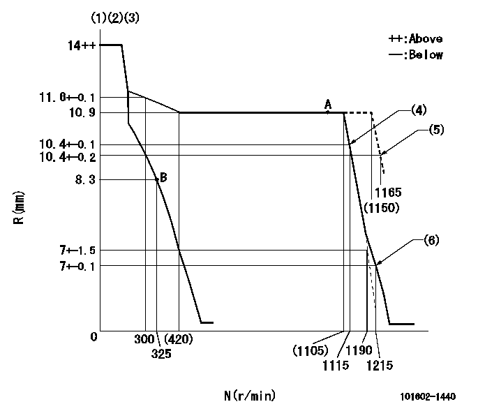
N:Pump speed
R:Rack position (mm)
(1)Notch fixed: K
(2)Tolerance for racks not indicated: +-0.05mm.
(3)Torque spring does not operate.
(4)Main spring setting
(5)Set at delivery
(6)Set idle sub-spring
----------
K=8
----------
----------
K=8
----------
Speed control lever angle
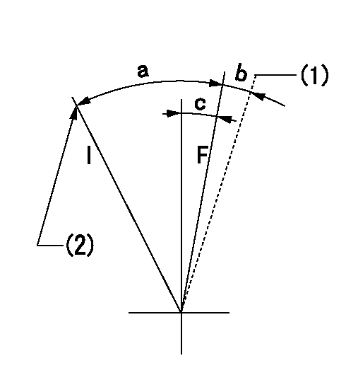
F:Full speed
I:Idle
(1)At delivery
(2)Stopper bolt setting
----------
----------
a=(20deg)+-5deg b=(2deg) c=(5deg)+-5deg
----------
----------
a=(20deg)+-5deg b=(2deg) c=(5deg)+-5deg
Stop lever angle

N:Pump normal
S:Stop the pump.
----------
----------
a=26deg+-5deg b=53deg+-5deg
----------
----------
a=26deg+-5deg b=53deg+-5deg
Timing setting

(1)Pump vertical direction
(2)Position of coupling's tooth at No 1 cylinder's beginning of injection
(3)B.T.D.C.: aa
(4)-
----------
aa=11deg
----------
a=(1deg)
----------
aa=11deg
----------
a=(1deg)
Information:
Illustration 3 g01077676
(1) HEUI pump (2) Fuel transfer pump (9) Service bolt (10) Seals (11) Seal (12) Check valve assemblies (Qty 7)Removing the Check Valve Assemblies from the HEUI Pump
Remove the two high pressure seals (10). Discard the two seals. Refer to Illustration 3.Note: Take caution in order to avoid wiping any debris into the pump.
Remove the seal (11) from the bearing on the fuel transfer pump. Discard the seal. Refer to Illustration 3.
Remove the seven check valve assemblies (12) from the HEUI pump by using Tooling (A). Refer to Illustration 3.Note: Take caution in order to avoid wiping any debris into the pump.
Inspect all check valve assemblies (12) for broken springs by using the following procedure.
Place the flat end of the check valve on a work bench so that the valve is positioned vertically.
Press on the check valve poppet (13) with a small cross tip screwdriver and then release the check valve poppet. There should be some resistance from the spring in the check valve. The poppet should return to the initial position after releasing. Refer to Illustration 4.
Illustration 4 g01077708
(12) Check valve assembly (13) Check valve poppet
If any of the valve springs are broken, do not advance. Stop the rework procedure. Replace the HEUI pump.
If none of the valve springs are broken, proceed to the next section.Installing Check Valve Assemblies into the HEUI Pump
Install seven new 254-4302 Check Valve Assemblies (12) that are found in the 254-4334 Check Valve Kit .
Insert the check valve assemblies by hand and press on the back of the valve until the valve is fully seated in the barrel.
Tighten each valve to 9.0 1.5 N m (80 13 lb in) by using an appropriate torque wrench and Tooling (A) .Note: The check valve assemblies must be torqued to the correct specifications. Failing to apply the correct torque could result in loosening of the valve or cracking of the valve in the field.
In order to ensure that all valves are torqued, repeat Step 3.Installing the Fuel Transfer Pump onto the HEUI Pump
Install the two new 239-2402 Seals (10) on the back face of the HEUI pump (1). Refer to Illustration 5.
Illustration 5 g01077898
(1) HEUI pump (10) 239-2402 Seals
Install a new 179-8128 Seal (11) on the fuel transfer pump (2). Refer to Illustration 6. Use 1U-6396 O-Ring Assembly Compound in order to hold the seal in place during assembly. Ensure that the seal is completely seated.
Illustration 6 g01077908
(2) Fuel transfer pump (11) 179-8128 Seal
Do not remove the service bolt. Position the fuel transfer pump on the HEUI pump. Be sure to properly align the drive tang on the fuel transfer pump with the drive slot on the HEUI pump.Note: Failure to align the drive tang prior to the installation of the fuel transfer pump will not allow proper assembly of the two pumps.
Install the three mounting bolts (7) for the fuel transfer pump (2). Tighten the bolts to a torque of 4.0 0.2 N m (35 1.5