Information injection-pump assembly
BOSCH
F 01G 09U 038
f01g09u038
ZEXEL
101602-1401
1016021401
Rating:
Include in #2:
104057-3210
as _
Cross reference number
BOSCH
F 01G 09U 038
f01g09u038
ZEXEL
101602-1401
1016021401
Zexel num
Bosch num
Firm num
Name
Calibration Data:
Adjustment conditions
Test oil
1404 Test oil ISO4113 or {SAEJ967d}
1404 Test oil ISO4113 or {SAEJ967d}
Test oil temperature
degC
40
40
45
Nozzle and nozzle holder
105780-8140
Bosch type code
EF8511/9A
Nozzle
105780-0000
Bosch type code
DN12SD12T
Nozzle holder
105780-2080
Bosch type code
EF8511/9
Opening pressure
MPa
17.2
Opening pressure
kgf/cm2
175
Injection pipe
Outer diameter - inner diameter - length (mm) mm 6-2-600
Outer diameter - inner diameter - length (mm) mm 6-2-600
Overflow valve
131424-5520
Overflow valve opening pressure
kPa
255
221
289
Overflow valve opening pressure
kgf/cm2
2.6
2.25
2.95
Tester oil delivery pressure
kPa
157
157
157
Tester oil delivery pressure
kgf/cm2
1.6
1.6
1.6
Direction of rotation (viewed from drive side)
Left L
Left L
Injection timing adjustment
Direction of rotation (viewed from drive side)
Left L
Left L
Injection order
1-5-3-6-
2-4
Pre-stroke
mm
4.5
4.45
4.55
Beginning of injection position
Governor side NO.1
Governor side NO.1
Difference between angles 1
Cal 1-5 deg. 60 59.5 60.5
Cal 1-5 deg. 60 59.5 60.5
Difference between angles 2
Cal 1-3 deg. 120 119.5 120.5
Cal 1-3 deg. 120 119.5 120.5
Difference between angles 3
Cal 1-6 deg. 180 179.5 180.5
Cal 1-6 deg. 180 179.5 180.5
Difference between angles 4
Cyl.1-2 deg. 240 239.5 240.5
Cyl.1-2 deg. 240 239.5 240.5
Difference between angles 5
Cal 1-4 deg. 300 299.5 300.5
Cal 1-4 deg. 300 299.5 300.5
Injection quantity adjustment
Adjusting point
A
Rack position
10.2
Pump speed
r/min
1000
1000
1000
Average injection quantity
mm3/st.
93.5
92.5
94.5
Max. variation between cylinders
%
0
-2.5
2.5
Basic
*
Fixing the lever
*
Injection quantity adjustment_02
Adjusting point
B
Rack position
7.8+-0.5
Pump speed
r/min
425
425
425
Average injection quantity
mm3/st.
10.5
9
12
Max. variation between cylinders
%
0
-15
15
Fixing the rack
*
Test data Ex:
Governor adjustment
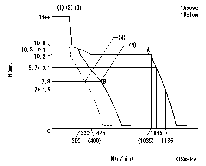
N:Pump speed
R:Rack position (mm)
(1)Notch fixed: K
(2)Tolerance for racks not indicated: +-0.05mm.
(3)Torque spring does not operate.
(4)Set idle sub-spring
(5)Main spring setting
----------
K=7
----------
----------
K=7
----------
Speed control lever angle

F:Full speed
I:Idle
(1)Stopper bolt setting
----------
----------
a=(19deg)+-5deg b=(1deg)+-5deg
----------
----------
a=(19deg)+-5deg b=(1deg)+-5deg
Stop lever angle

N:Pump normal
S:Stop the pump.
----------
----------
a=25deg+-5deg b=53deg+-5deg
----------
----------
a=25deg+-5deg b=53deg+-5deg
Timing setting

(1)Pump vertical direction
(2)Position of coupling's tooth at No 1 cylinder's beginning of injection
(3)B.T.D.C.: aa
(4)-
----------
aa=11deg
----------
a=(1deg)
----------
aa=11deg
----------
a=(1deg)
Information:
Illustration 4 g06005614
(A) Hydraulic tank drain
Drain the hydraulic tank. Refer to Illustration 4.Note: After draining, if a significant number of metal particles are visible in the tank, contact BCP STTT support through the DSN for guidance before proceeding further.
Drain the hydraulic cylinders.
Disconnect and drain the lines at all cylinders.
Retract and extend the cylinder rods to evacuate cylinders.
Illustration 5 g06005620
(B) Inlet lines
(C) Outlet lines
Drain the hydraulic oil cooler. Refer to Illustration 5.
Remove inlet and outlet lines at cooler.
Drain the cooler and the lines.Note: Ensure that the cooler has been drained.
Illustration 6 g06005623
(D) Case plug
Drain the hystat pumps. Refer to Illustration 6.
Remove case plug (D) on the rear right side of the pump.
Drain pumps and suction remaining oil from pump housing.Note: Ensure that the pump case has been drained.
Illustration 7 g06005628
(E) Parking brake lines
Drain the parking brake lines. Refer to Illustration 7.
Disconnect and drain the parking brake line (E) at the bottom of the pumps.
Disconnect and drain the right-hand brake line (E) connection.
Illustration 8 g06005631
(F) Case drain lines and hystat motors
Drain the drive motors. Refer to Illustration 8.
Disconnect the case drain lines at the hystat motors.Note: Ensure that the motor cases have been drained.
Illustration 9 g06005637
Standard Machine
(G) Hydraulic filter
Illustration 10 g06005640
Winch Machine
(G) Hydraulic filter
(H) Winch hydraulic filter
Drain the hydraulic filters. Refer to Illustrations 9 and 10.
Replace the standard and winch (if equipped) filters with each drain cycle.
Check filters for metal particles.
Refill the hydraulic system, repeat Steps 2 through 8, running and warming the hydraulic oil between drain, fill, and filter change cycles. Cycle all cylinders and travel circuits after every fill cycle to achieve full circulation throughout the hydraulic and power train systems with the new oil. Perform SOS check after each run cycle and follow standard SOS guidelines, specifically checking for DEF.Note: Typically takes 5 to 6 drain/refill cycles to clean the hydraulic system and get a clean SOS sample. Clean oil will be red and transparent or clear / light yellow and transparent. If there is any milky appearance to the color, repeat Steps 2 through 9.
Confirm that charge pressure can be set and maintained to specification, especially at pump stall.
Recalibrate the hystat pumps and drive motors, ensuring that calibration is successfully completed. Confirm that the hystat pump pressure can be adjusted to the correct specificationNote: Refer to Testing and Adjusting, UENR4089, "D3K2, D4K2, and D5K2 Track-Type Tractor Systems" for the correct procedure and specification.
Illustration 11 g06005642
(1) 484-5902 Diesel Exhaust Fluid (DEF) film(U.S.)(Shown)
(1A) 393-2614 Diesel Exhaust Fluid (DEF) film(International)
(2) 484-5903 Hydraulic oil film
(3) 430-3036 Diesel Exhaust Fluid (DEF) Gauge (Inst) film(Inside Door)
Illustration 12 g06237577
(1) 484-5902 Diesel Exhaust Fluid (DEF) film
(1A) 393-2614 Diesel Exhaust Fluid (DEF) film (International)
(2) 484-5903 Hydraulic oil film
Illustration 13 g06166475
(3) 430-3036 Diesel Exhaust Fluid (DEF) Gauge (Inst) film
New extra DEF (1), hydraulic oil (2), and DEF gauge instruction (3) films will be used in production. Refer to Table 2 for the affected machines that require the new films. For the film locations, refer to Illustrations 11, 12, and 13.Note: Adding these stickers to reduce chances of a recurrence of this issue is recommended.Note: Refer