Information injection-pump assembly
BOSCH
F 01G 09U 037
f01g09u037
ZEXEL
101602-1400
1016021400

Rating:
Service parts 101602-1400 INJECTION-PUMP ASSEMBLY:
1.
_

5.
AUTOM. ADVANCE MECHANIS
6.
COUPLING PLATE
8.
_
9.
_
11.
Nozzle and Holder
ME078067
12.
Open Pre:MPa(Kqf/cm2)
17.7{180}
15.
NOZZLE SET
Include in #1:
101602-1400
as INJECTION-PUMP ASSEMBLY
Include in #2:
104140-0080
as _
Cross reference number
BOSCH
F 01G 09U 037
f01g09u037
ZEXEL
101602-1400
1016021400
Zexel num
Bosch num
Firm num
Name
Calibration Data:
Adjustment conditions
Test oil
1404 Test oil ISO4113 or {SAEJ967d}
1404 Test oil ISO4113 or {SAEJ967d}
Test oil temperature
degC
40
40
45
Nozzle and nozzle holder
105780-8140
Bosch type code
EF8511/9A
Nozzle
105780-0000
Bosch type code
DN12SD12T
Nozzle holder
105780-2080
Bosch type code
EF8511/9
Opening pressure
MPa
17.2
Opening pressure
kgf/cm2
175
Injection pipe
Outer diameter - inner diameter - length (mm) mm 6-2-600
Outer diameter - inner diameter - length (mm) mm 6-2-600
Overflow valve
131424-5520
Overflow valve opening pressure
kPa
255
221
289
Overflow valve opening pressure
kgf/cm2
2.6
2.25
2.95
Tester oil delivery pressure
kPa
157
157
157
Tester oil delivery pressure
kgf/cm2
1.6
1.6
1.6
Direction of rotation (viewed from drive side)
Left L
Left L
Injection timing adjustment
Direction of rotation (viewed from drive side)
Left L
Left L
Injection order
1-5-3-6-
2-4
Pre-stroke
mm
4.5
4.45
4.55
Beginning of injection position
Governor side NO.1
Governor side NO.1
Difference between angles 1
Cal 1-5 deg. 60 59.5 60.5
Cal 1-5 deg. 60 59.5 60.5
Difference between angles 2
Cal 1-3 deg. 120 119.5 120.5
Cal 1-3 deg. 120 119.5 120.5
Difference between angles 3
Cal 1-6 deg. 180 179.5 180.5
Cal 1-6 deg. 180 179.5 180.5
Difference between angles 4
Cyl.1-2 deg. 240 239.5 240.5
Cyl.1-2 deg. 240 239.5 240.5
Difference between angles 5
Cal 1-4 deg. 300 299.5 300.5
Cal 1-4 deg. 300 299.5 300.5
Injection quantity adjustment
Adjusting point
A
Rack position
10.2
Pump speed
r/min
1000
1000
1000
Average injection quantity
mm3/st.
93.5
92.5
94.5
Max. variation between cylinders
%
0
-2.5
2.5
Basic
*
Fixing the lever
*
Injection quantity adjustment_02
Adjusting point
B
Rack position
7.8+-0.5
Pump speed
r/min
425
425
425
Average injection quantity
mm3/st.
10.5
9
12
Max. variation between cylinders
%
0
-15
15
Fixing the rack
*
Test data Ex:
Governor adjustment
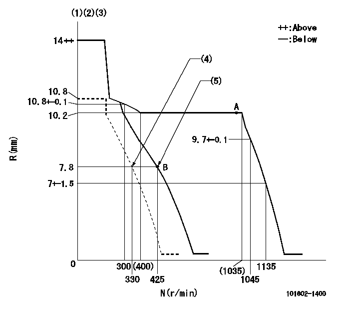
N:Pump speed
R:Rack position (mm)
(1)Notch fixed: K
(2)Tolerance for racks not indicated: +-0.05mm.
(3)Torque spring does not operate.
(4)Set idle sub-spring
(5)Main spring setting
----------
K=7
----------
----------
K=7
----------
Speed control lever angle
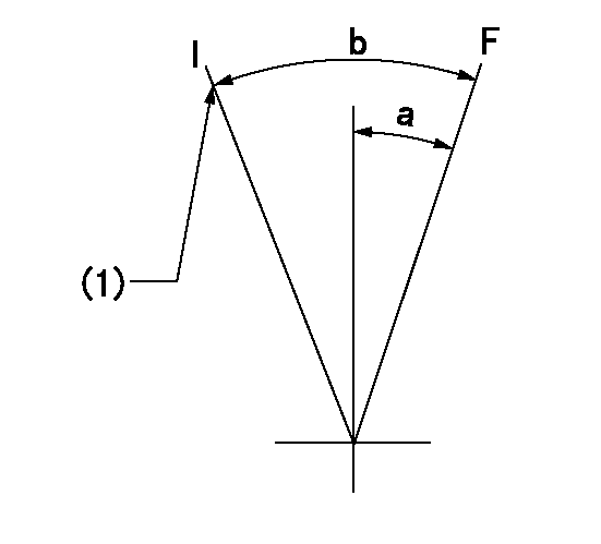
F:Full speed
I:Idle
(1)Stopper bolt setting
----------
----------
a=(1deg)+-5deg b=(19deg)+-5deg
----------
----------
a=(1deg)+-5deg b=(19deg)+-5deg
Stop lever angle

N:Pump normal
S:Stop the pump.
----------
----------
a=26deg+-5deg b=53deg+-5deg
----------
----------
a=26deg+-5deg b=53deg+-5deg
Timing setting

(1)Pump vertical direction
(2)Position of timer's tooth at No 1 cylinder's beginning of injection
(3)B.T.D.C.: aa
(4)-
----------
aa=10deg
----------
a=(1deg)
----------
aa=10deg
----------
a=(1deg)
Information:
Illustration 1 g01090281 (1) Water pump drive gear
Illustration 2 g00537659
Stub shaft for cluster gear
(2) Cluster gear Apply 9S-3263 Thread Lock Compound to the five bolts for the stub shaft. Tighten the five bolts for the stub shaft in the following sequence. See Illustration 2 for the numbering of the bolts. ... 1, 3, 4, 5, 2, 1, 2, 3, 4, 5, 1Apply 9S-3263 Thread Lock Compound to the four bolts that fasten the cluster gear to the stub shaft. Tighten the four bolts that fasten the cluster gear to the stub shaft to the following torque. ... 55 10 N m (41