Information injection-pump assembly
BOSCH
9 400 610 567
9400610567
ZEXEL
101602-1172
1016021172
MITSUBISHI
ME070931
me070931
Rating:
Service parts 101602-1172 INJECTION-PUMP ASSEMBLY:
1.
_
5.
AUTOM. ADVANCE MECHANIS
6.
COUPLING PLATE
8.
_
9.
_
11.
Nozzle and Holder
ME047882
12.
Open Pre:MPa(Kqf/cm2)
17.7{180}

15.
NOZZLE SET
Cross reference number
BOSCH
9 400 610 567
9400610567
ZEXEL
101602-1172
1016021172
MITSUBISHI
ME070931
me070931
Zexel num
Bosch num
Firm num
Name
101602-1172
9 400 610 567
ME070931 MITSUBISHI
INJECTION-PUMP ASSEMBLY
6D16T * K 14BF INJECTION PUMP ASSY PE6AD PE
6D16T * K 14BF INJECTION PUMP ASSY PE6AD PE
Calibration Data:
Adjustment conditions
Test oil
1404 Test oil ISO4113 or {SAEJ967d}
1404 Test oil ISO4113 or {SAEJ967d}
Test oil temperature
degC
40
40
45
Nozzle and nozzle holder
105780-8140
Bosch type code
EF8511/9A
Nozzle
105780-0000
Bosch type code
DN12SD12T
Nozzle holder
105780-2080
Bosch type code
EF8511/9
Opening pressure
MPa
17.2
Opening pressure
kgf/cm2
175
Injection pipe
Outer diameter - inner diameter - length (mm) mm 6-2-600
Outer diameter - inner diameter - length (mm) mm 6-2-600
Overflow valve
131424-5520
Overflow valve opening pressure
kPa
255
221
289
Overflow valve opening pressure
kgf/cm2
2.6
2.25
2.95
Tester oil delivery pressure
kPa
157
157
157
Tester oil delivery pressure
kgf/cm2
1.6
1.6
1.6
Direction of rotation (viewed from drive side)
Left L
Left L
Injection timing adjustment
Direction of rotation (viewed from drive side)
Left L
Left L
Injection order
1-5-3-6-
2-4
Pre-stroke
mm
4.2
4.15
4.25
Beginning of injection position
Governor side NO.1
Governor side NO.1
Difference between angles 1
Cal 1-5 deg. 60 59.5 60.5
Cal 1-5 deg. 60 59.5 60.5
Difference between angles 2
Cal 1-3 deg. 120 119.5 120.5
Cal 1-3 deg. 120 119.5 120.5
Difference between angles 3
Cal 1-6 deg. 180 179.5 180.5
Cal 1-6 deg. 180 179.5 180.5
Difference between angles 4
Cyl.1-2 deg. 240 239.5 240.5
Cyl.1-2 deg. 240 239.5 240.5
Difference between angles 5
Cal 1-4 deg. 300 299.5 300.5
Cal 1-4 deg. 300 299.5 300.5
Injection quantity adjustment
Adjusting point
A
Rack position
9.3
Pump speed
r/min
750
750
750
Average injection quantity
mm3/st.
93.5
90
97
Max. variation between cylinders
%
0
-3
3
Basic
*
Fixing the rack
*
Injection quantity adjustment_02
Adjusting point
-
Rack position
6.6+-0.5
Pump speed
r/min
350
350
350
Average injection quantity
mm3/st.
10
8.5
11.5
Max. variation between cylinders
%
0
-15
15
Fixing the rack
*
Remarks
Adjust only variation between cylinders; adjust governor according to governor specifications.
Adjust only variation between cylinders; adjust governor according to governor specifications.
Test data Ex:
Governor adjustment
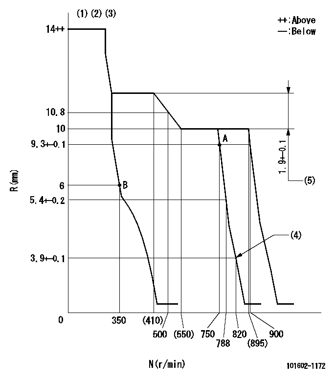
N:Pump speed
R:Rack position (mm)
(1)Target notch: K
(2)Tolerance for racks not indicated: +-0.05mm.
(3)Torque spring does not operate.
(4)Set idle sub-spring
(5)Rack difference between N = N1 and N = N2
----------
K=17 N1=700r/min N2=350r/min
----------
----------
K=17 N1=700r/min N2=350r/min
----------
Speed control lever angle
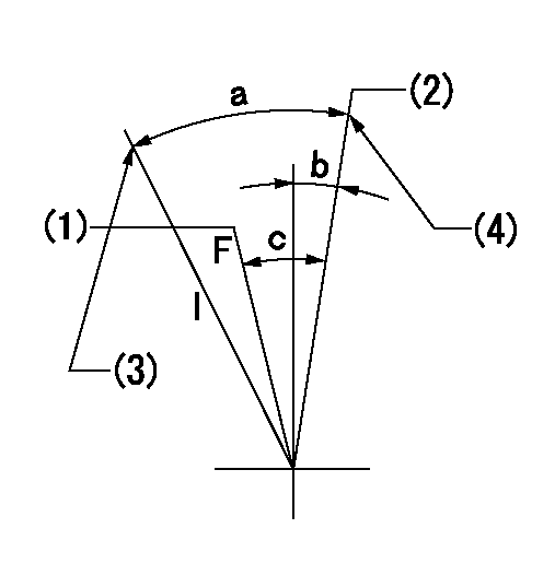
F:Full speed
I:Idle
(1)Pump speed = aa
(2)Pump speed = bb
(3)Stopper bolt setting
(4)Stopper bolt setting
----------
aa=750r/min bb=900r/min
----------
a=23deg+-5deg b=1deg+-5deg c=6deg+-5deg
----------
aa=750r/min bb=900r/min
----------
a=23deg+-5deg b=1deg+-5deg c=6deg+-5deg
Stop lever angle

N:Pump normal
S:Stop the pump.
----------
----------
a=26deg+-5deg b=53deg+-5deg
----------
----------
a=26deg+-5deg b=53deg+-5deg
Timing setting

(1)Pump vertical direction
(2)Position of coupling's tooth at No 1 cylinder's beginning of injection
(3)B.T.D.C.: aa
(4)-
----------
aa=11deg
----------
a=(1deg)
----------
aa=11deg
----------
a=(1deg)
Information:
Personal injury can result from being struck by parts propelled by a released spring force.Make sure to wear all necessary protective equipment.Follow the recommended procedure and use all recommended tooling to release the spring force.
Care must be taken to ensure that fluids are contained during performance of inspection, maintenance, testing, adjusting and repair of the product. Be prepared to collect the fluid with suitable containers before opening any compartment or disassembling any component containing fluids.Dispose of all fluids according to local regulations and mandates.
If possible, take the fuel injection pump to a clean work area.
Clean the outside surfaces of the fuel injection pump.
Illustration 1 g03117860
Typical example
Place a suitable container under the fuel injection pump to collect any fuel from the fuel injection pump. Use a suitable tool to loosen the drain plug (1). If necessary, retain the fuel collected for analysis if required.
Illustration 2 g03117878
Typical example
Use a suitable pair of pliers to remove the throttle return spring (2).Note: Care should be taken when the spring is removed.
Illustration 3 g03117896
Typical example
Loosen self-locking nut (3). Do not remove the nut.
Illustration 4 g03117916
Typical example
Use a suitable pair of pliers to lift and disconnect throttle spring (4). Remove self-locking nut (3), washer, upper retainer, spring, lower retainer, spacer, lever, and dust cap.Note: Care should be taken when the spring is removed.
Illustration 5 g03117938
Typical example
Remove four screws (6) in the governor cover (7). Gently push the throttle shaft (5) down into the cover (7).
Illustration 6 g03117956
Typical example
To inspect the internal components of the fuel injection pump, gently lift and rotate the cover (7).Note: The cover is still connected internally, if resistance is felt, lower the cover and move the cover backwards. Attempt to lift the cover again.
Inspect the internal components of the fuel injection pump. Refer to steps 9a and 9b.
Illustration 7 g03117961
Typical example
If good quality fuel is being used, the components will be clean. Refer to illustration 7. Take photographs of the identification plate of the fuel injection pump and any evidence found. Attach the photographs to support the claim story.
Illustration 8 g03118119
Typical example
Illustration 9 g03118121
Typical example
If the injection pump has been run with excessive water in the fuel, there will be signs of rust and oxidization of the steel components. Refer to illustration 8. Fuel with dirt ingress will show a build-up of dirt on the components. Refer to illustration 9.Note: Issues with the fuel injection pump that are due to dirt and water void Caterpillar warranty. Advise the customer on the correct fuel, maintenance, and fuel storage procedures. Refer to the relevant Operation and Maintenance Manual for more information.If the fuel injection pump shows signs that contaminated fuel is the root cause of the problem, the evidence can be shown to the customer immediately.After the fuel injection pump has been inspected, the fuel injection pump must not be used in service.Rebuild the fuel injection pump. Refer to steps 1 to 6
Lower the cover (7) back into position. Ensure the throttle shaft (5), has been returned to the original position.
Install the four screws (6) to the cover (7). Tighten the
Have questions with 101602-1172?
Group cross 101602-1172 ZEXEL
Mitsubishi
Mitsubishi
Mitsubishi
101602-1172
9 400 610 567
ME070931
INJECTION-PUMP ASSEMBLY
6D16T
6D16T