Information injection-pump assembly
BOSCH
F 01G 09U 036
f01g09u036
ZEXEL
101602-1171
1016021171

Rating:
Service parts 101602-1171 INJECTION-PUMP ASSEMBLY:
1.
_
5.
AUTOM. ADVANCE MECHANIS
6.
COUPLING PLATE
8.
_
9.
_
11.
Nozzle and Holder
ME047437
12.
Open Pre:MPa(Kqf/cm2)
17.7{180}
15.
NOZZLE SET
Cross reference number
BOSCH
F 01G 09U 036
f01g09u036
ZEXEL
101602-1171
1016021171
Zexel num
Bosch num
Firm num
Name
Calibration Data:
Adjustment conditions
Test oil
1404 Test oil ISO4113 or {SAEJ967d}
1404 Test oil ISO4113 or {SAEJ967d}
Test oil temperature
degC
40
40
45
Nozzle and nozzle holder
105780-8140
Bosch type code
EF8511/9A
Nozzle
105780-0000
Bosch type code
DN12SD12T
Nozzle holder
105780-2080
Bosch type code
EF8511/9
Opening pressure
MPa
17.2
Opening pressure
kgf/cm2
175
Injection pipe
Outer diameter - inner diameter - length (mm) mm 6-2-600
Outer diameter - inner diameter - length (mm) mm 6-2-600
Overflow valve
131424-5520
Overflow valve opening pressure
kPa
255
221
289
Overflow valve opening pressure
kgf/cm2
2.6
2.25
2.95
Tester oil delivery pressure
kPa
157
157
157
Tester oil delivery pressure
kgf/cm2
1.6
1.6
1.6
Direction of rotation (viewed from drive side)
Left L
Left L
Injection timing adjustment
Direction of rotation (viewed from drive side)
Left L
Left L
Injection order
1-5-3-6-
2-4
Pre-stroke
mm
4.2
4.15
4.25
Beginning of injection position
Governor side NO.1
Governor side NO.1
Difference between angles 1
Cal 1-5 deg. 60 59.5 60.5
Cal 1-5 deg. 60 59.5 60.5
Difference between angles 2
Cal 1-3 deg. 120 119.5 120.5
Cal 1-3 deg. 120 119.5 120.5
Difference between angles 3
Cal 1-6 deg. 180 179.5 180.5
Cal 1-6 deg. 180 179.5 180.5
Difference between angles 4
Cyl.1-2 deg. 240 239.5 240.5
Cyl.1-2 deg. 240 239.5 240.5
Difference between angles 5
Cal 1-4 deg. 300 299.5 300.5
Cal 1-4 deg. 300 299.5 300.5
Injection quantity adjustment
Adjusting point
A
Rack position
9.5
Pump speed
r/min
750
750
750
Average injection quantity
mm3/st.
105.1
101.6
108.6
Max. variation between cylinders
%
0
-3
3
Basic
*
Fixing the rack
*
Injection quantity adjustment_02
Adjusting point
B
Rack position
6.9+-0.5
Pump speed
r/min
250
250
250
Average injection quantity
mm3/st.
10.6
9.1
12.1
Max. variation between cylinders
%
0
-15
15
Fixing the rack
*
Test data Ex:
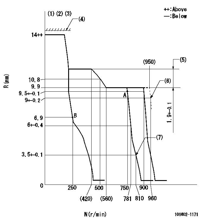
Governor adjustment

N:Pump speed
R:Rack position (mm)
(1)Target notch: K
(2)Tolerance for racks not indicated: +-0.05mm.
(3)Torque spring does not operate.
(4)RACK LIMIT not operating.
(5)Rack difference between N = N1 and N = N2
(6)At delivery
(7)Set idle sub-spring
----------
K=11 N1=700r/min N2=350r/min
----------
----------
K=11 N1=700r/min N2=350r/min
----------
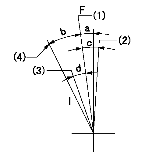
Speed control lever angle

F:Full speed
I:Idle
(1)Pump speed = aa
(2)At delivery
(3)Pump speed = bb
(4)Stopper bolt setting
----------
aa=900r/min bb=750r/min
----------
a=1deg+-5deg b=24deg+-5deg c=(2deg) d=5deg+-5deg
----------
aa=900r/min bb=750r/min
----------
a=1deg+-5deg b=24deg+-5deg c=(2deg) d=5deg+-5deg
Stop lever angle

N:Pump normal
S:Stop the pump.
(1)At delivery
----------
----------
a=26deg+-5deg b=53deg+-5deg
----------
----------
a=26deg+-5deg b=53deg+-5deg
Timing setting

(1)Pump vertical direction
(2)Position of coupling's tooth at No 1 cylinder's beginning of injection
(3)B.T.D.C.: aa
(4)-
----------
aa=11deg
----------
a=(0deg)
----------
aa=11deg
----------
a=(0deg)
Information:
C3.8 DPF
Illustration 14 g06047943
When the pin gauge is inserted into the cell hole, insert the gauge by lightly tapping on the pin with your finger tip. If the pin is pushed in by force, the pin can pierce through the ash and there would not be an accurate measurement.
After the DPF filter is cleaned, measure the depth of ash (depth of remaining ash) in 21 locations with a pin gauge of 0.5 mm to 1.0 mm in diameter, which is slightly less than the cell width at the positions.The minimum remaining ash depth is 106 mm (4.2 inch).The maximum depth is 140 mm (5.5 inch).
Table 2
Measurement Locations 21 Places
A 57 mm (2.2 inch)
B 57 mm (2.2 inch)
C 10 mm (0.4 inch)
D 35 mm (1.4 inch)
E 138 mm (5.4 inch)
F 35 mm (1.4 inch)
G 226 mm (8.9 inch)
If the depth of ash is out of the permissible range, the DPF filter cannot be reused. Replace the DPF filter with a new one.C3.3B DPF
Illustration 15 g03617080
When the pin gauge is inserted into the cell hole, insert the gauge by lightly tapping on the pin with your finger tip. If the pin is pushed in by force, the pin can pierce through the ash and there would not be an accurate measurement.
After the DPF filter is cleaned, measure the depth of ash (depth of remaining ash) in 25 locations with a pin gauge of 0.6 mm to 0.8 mm in diameter.C3.8 & C3.3B Engines - The minimum remaining ash depth is 119 mm (4.7 inch).
If the depth of ash is out of the permissible range, the DPF filter cannot be reused. Replace the DPF filter with a new one.C2.4 DPF
Illustration 16 g06047315
After the DPF filter is cleaned, measure the depth of ash (depth of remaining ash) in 16 locations with a pin gauge of 0.6 mm to 0.8 mm in diameter.C2.4 Engines (Naturally Aspirated) - The minimum remaining ash depth is 102 mm (4.0 inch).C2.4 Engines (Turbo) - The minimum remaining ash depth is 119 mm (4.7 inch).
If the depth of ash is out of the permissible range, the DPF filter cannot be reused. Replace the DPF filter with a new one.Assembly of the DPF Canister
Refer to the Disassembly and Assembly Manual, Diesel Particulate Filter - Assemble for the procedure to disassemble the DPF.
Illustration 17 g06047871
(14) Gas flow
Assemble the DPF filter in the right direction by referring to the arrow (14) on the side showing the flow of exhaust gas.
When installing the temperature sensor and differential pressure pipe, apply 4C-5599 Anti-Seize Compound to the threads.Note: Itis recommended to replacethe two differential pressure hoses.
If the engine is installed in the machine, refer to the machines Engine Supplement, Diesel Particulate Filter - Remove and Install for the procedure to install the DPF.Soot Load
The soot load reset should only be performed after the DPF is cleaned or a new DPF is installed. If the Soot Load Reset is performed any other times, soot load could cause the DPF to crack
