Information injection-pump assembly
ZEXEL
101602-1162
1016021162

Rating:
Service parts 101602-1162 INJECTION-PUMP ASSEMBLY:
1.
_
5.
AUTOM. ADVANCE MECHANIS
6.
COUPLING PLATE
8.
_
9.
_
11.
Nozzle and Holder
ME047437
12.
Open Pre:MPa(Kqf/cm2)
17.7{180}
15.
NOZZLE SET
Cross reference number
ZEXEL
101602-1162
1016021162
Zexel num
Bosch num
Firm num
Name
101602-1162
INJECTION-PUMP ASSEMBLY
6D16T 14BF PE6AD PE
6D16T 14BF PE6AD PE
Calibration Data:
Adjustment conditions
Test oil
1404 Test oil ISO4113 or {SAEJ967d}
1404 Test oil ISO4113 or {SAEJ967d}
Test oil temperature
degC
40
40
45
Nozzle and nozzle holder
105780-8140
Bosch type code
EF8511/9A
Nozzle
105780-0000
Bosch type code
DN12SD12T
Nozzle holder
105780-2080
Bosch type code
EF8511/9
Opening pressure
MPa
17.2
Opening pressure
kgf/cm2
175
Injection pipe
Outer diameter - inner diameter - length (mm) mm 6-2-600
Outer diameter - inner diameter - length (mm) mm 6-2-600
Overflow valve
131424-5520
Overflow valve opening pressure
kPa
255
221
289
Overflow valve opening pressure
kgf/cm2
2.6
2.25
2.95
Tester oil delivery pressure
kPa
157
157
157
Tester oil delivery pressure
kgf/cm2
1.6
1.6
1.6
Direction of rotation (viewed from drive side)
Left L
Left L
Injection timing adjustment
Direction of rotation (viewed from drive side)
Left L
Left L
Injection order
1-5-3-6-
2-4
Pre-stroke
mm
4.2
4.15
4.25
Beginning of injection position
Governor side NO.1
Governor side NO.1
Difference between angles 1
Cal 1-5 deg. 60 59.5 60.5
Cal 1-5 deg. 60 59.5 60.5
Difference between angles 2
Cal 1-3 deg. 120 119.5 120.5
Cal 1-3 deg. 120 119.5 120.5
Difference between angles 3
Cal 1-6 deg. 180 179.5 180.5
Cal 1-6 deg. 180 179.5 180.5
Difference between angles 4
Cyl.1-2 deg. 240 239.5 240.5
Cyl.1-2 deg. 240 239.5 240.5
Difference between angles 5
Cal 1-4 deg. 300 299.5 300.5
Cal 1-4 deg. 300 299.5 300.5
Injection quantity adjustment
Adjusting point
A
Rack position
9.5
Pump speed
r/min
750
750
750
Average injection quantity
mm3/st.
105.1
101.6
108.6
Max. variation between cylinders
%
0
-3
3
Basic
*
Fixing the rack
*
Injection quantity adjustment_02
Adjusting point
B
Rack position
6.9+-0.5
Pump speed
r/min
250
250
250
Average injection quantity
mm3/st.
10.6
9.1
12.1
Max. variation between cylinders
%
0
-15
15
Fixing the rack
*
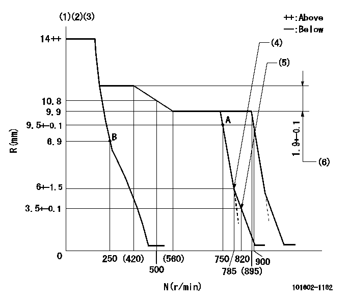
Test data Ex:
Governor adjustment

N:Pump speed
R:Rack position (mm)
(1)Notch fixed: K
(2)Tolerance for racks not indicated: +-0.05mm.
(3)Supplied with torque spring not set.
(4)Main spring setting
(5)Set idle sub-spring
(6)Rack difference between N = N1 and N = N2
----------
K=13 N1=700r/min N2=350r/min
----------
----------
K=13 N1=700r/min N2=350r/min
----------
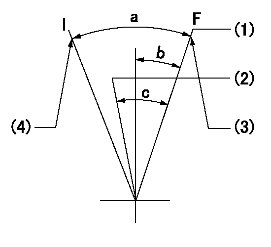
Speed control lever angle

F:Full speed
I:Idle
(1)Pump speed = aa
(2)Pump speed = bb
(3)Stopper bolt setting
(4)Stopper bolt setting
----------
aa=900r/min bb=750r/min
----------
a=(27deg)+-5deg b=(1deg)+-5deg c=(6deg)+-5deg
----------
aa=900r/min bb=750r/min
----------
a=(27deg)+-5deg b=(1deg)+-5deg c=(6deg)+-5deg
Stop lever angle

N:Pump normal
S:Stop the pump.
----------
----------
a=26deg+-5deg b=53deg+-5deg
----------
----------
a=26deg+-5deg b=53deg+-5deg
Timing setting

(1)Pump vertical direction
(2)Position of coupling's tooth at No 1 cylinder's beginning of injection
(3)B.T.D.C.: aa
(4)-
----------
aa=11deg
----------
a=(1deg)
----------
aa=11deg
----------
a=(1deg)
Information:
Safety Precautions
Make sure that you disconnect all power to the monitor before performing any of the procedures that follow.
Disconnect all electrical power from the monitor before removing components. Failure to disconnect the power could result in severe electrical shock or damage to the monitor. An electrical shock can cause severe personal injury or death.
Removing The Flat Panel Display
The monitor has 10 screws that secure the flat panel display to the chassis.In order to remove the flat panel display, perform the following procedure:
Remove the top cover of the monitor. Refer to Testing and Adjusting, "Cover - Remove" for details on removing the top cover.
Illustration 1 g00858319
Central Processing Unit (CPU) Card (1) Display Connector
Disconnect the video cable that is connected to the display connector (1) on the CPU card.
Illustration 2 g00858320
(2) Power Supply (3) Touchscreen Controller Board (4) Pin 1 on the touchscreen cable connector
If the unit is equipped with a touchscreen, remove the back cover of the monitor. Refer to Testing and Adjusting, "Cover - Remove" for details on removing the back cover.Disconnect the touchscreen cable (flexible cable) from the touchscreen controller board (3). The touchscreen controller board (3) is attached to the outside of the power supply (2) .
Illustration 3 g00858321
10 Screws
Remove the 10 screws that secure the flat panel display to the chassis of the monitor.
Illustration 4 g00858322
(5) Video Cable (6) Backlight Power Supply (7) Indicator Board (8) Backlight TubesNote: This illustration shows the 264 mm (10.4 inch) version. The backlight power supply board (6) on the 307 mm (12.1 inch) version is mounted on a separate detachable bracket. The backlight power supply board is not mounted on the back of the display.
Carefully pull the flat panel display away from the chassis and disconnect the following connectors from the flat panel display:
Indicator connector from the indicator board (7)
Power cable that is attached to the backlight power supply (6) Replacing The Backlight Tubes
The backlight assembly contains two backlight tubes (8), which must be replaced. The replacement tubes are 203-7814 Boards .In order to replace the backlight tubes (8), perform the following procedure:
Disconnect the backlight tube connectors from the backlight power supply (6) .
Remove the two screws that are holding each backlight tube (8) in place.
Slide the tube to the left and gently pull the tube out of the assembly.
Insert the replacement backlight tube into the slot. Slide the tube to the right until the holes for the screws are aligned. Replace the screws.
Reattach the backlight tube connectors to the backlight power supply (6) .
Reattach the indicator connector to the indicator board (7) and the power cable to the backlight controller board.
Reattach the display cable to the CPU card. Attach the touchscreen cable to the touchscreen controller board (3) .
Reattach the display assembly to the unit. Use the 10 screws.
Replace the top cover of the unit. Replace the back cover of the unit.
Have questions with 101602-1162?
Group cross 101602-1162 ZEXEL
101602-1162
INJECTION-PUMP ASSEMBLY
6D16T
6D16T
