Information injection-pump assembly
ZEXEL
101602-1160
1016021160

Rating:
Service parts 101602-1160 INJECTION-PUMP ASSEMBLY:
1.
_
5.
AUTOM. ADVANCE MECHANIS
6.
COUPLING PLATE
8.
_
9.
_
11.
Nozzle and Holder
ME047437
12.
Open Pre:MPa(Kqf/cm2)
17.7{180}
15.
NOZZLE SET
Cross reference number
ZEXEL
101602-1160
1016021160
Zexel num
Bosch num
Firm num
Name
101602-1160
INJECTION-PUMP ASSEMBLY
Calibration Data:
Adjustment conditions
Test oil
1404 Test oil ISO4113 or {SAEJ967d}
1404 Test oil ISO4113 or {SAEJ967d}
Test oil temperature
degC
40
40
45
Nozzle and nozzle holder
105780-8140
Bosch type code
EF8511/9A
Nozzle
105780-0000
Bosch type code
DN12SD12T
Nozzle holder
105780-2080
Bosch type code
EF8511/9
Opening pressure
MPa
17.2
Opening pressure
kgf/cm2
175
Injection pipe
Outer diameter - inner diameter - length (mm) mm 6-2-600
Outer diameter - inner diameter - length (mm) mm 6-2-600
Overflow valve
131425-5520
Overflow valve opening pressure
kPa
255
221
289
Overflow valve opening pressure
kgf/cm2
2.6
2.25
2.95
Tester oil delivery pressure
kPa
157
157
157
Tester oil delivery pressure
kgf/cm2
1.6
1.6
1.6
Direction of rotation (viewed from drive side)
Left L
Left L
Injection timing adjustment
Direction of rotation (viewed from drive side)
Left L
Left L
Injection order
1-5-3-6-
2-4
Pre-stroke
mm
4.2
4.15
4.25
Beginning of injection position
Governor side NO.1
Governor side NO.1
Difference between angles 1
Cal 1-5 deg. 60 59.5 60.5
Cal 1-5 deg. 60 59.5 60.5
Difference between angles 2
Cal 1-3 deg. 120 119.5 120.5
Cal 1-3 deg. 120 119.5 120.5
Difference between angles 3
Cal 1-6 deg. 180 179.5 180.5
Cal 1-6 deg. 180 179.5 180.5
Difference between angles 4
Cyl.1-2 deg. 240 239.5 240.5
Cyl.1-2 deg. 240 239.5 240.5
Difference between angles 5
Cal 1-4 deg. 300 299.5 300.5
Cal 1-4 deg. 300 299.5 300.5
Injection quantity adjustment
Adjusting point
A
Rack position
9.5
Pump speed
r/min
750
750
750
Average injection quantity
mm3/st.
105.1
101.6
108.6
Max. variation between cylinders
%
0
-3
3
Basic
*
Fixing the rack
*
Injection quantity adjustment_02
Adjusting point
B
Rack position
6.9+-0.5
Pump speed
r/min
250
250
250
Average injection quantity
mm3/st.
10.6
9.1
12.1
Max. variation between cylinders
%
0
-15
15
Fixing the rack
*
Test data Ex:
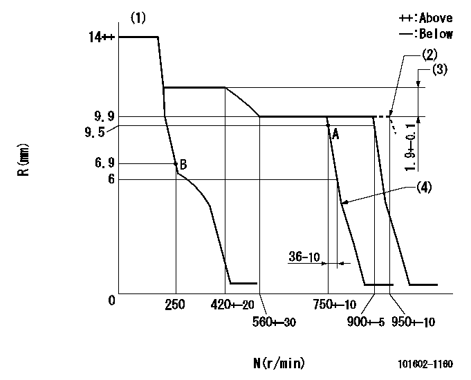
Governor adjustment

N:Pump speed
R:Rack position (mm)
(1)Target notch: K
(2)At shipping
(3)Rack difference between N = N1 and N = N2
(4)Idle sub spring setting: L1.
----------
K=11 N1=700r/min N2=350r/min L1=4.5+-0.1mm
----------
----------
K=11 N1=700r/min N2=350r/min L1=4.5+-0.1mm
----------
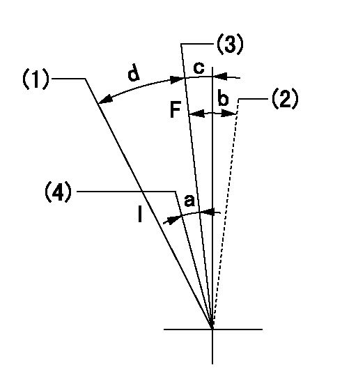
Speed control lever angle

F:Full speed
I:Idle
(1)Stopper bolt setting
(2)At shipping
(3)Set the pump speed at aa
(4)Set the pump speed at bb.
----------
aa=900r/min bb=750r/min
----------
a=5deg+-5deg b=(2deg) c=1deg+-5deg d=24deg+-5deg
----------
aa=900r/min bb=750r/min
----------
a=5deg+-5deg b=(2deg) c=1deg+-5deg d=24deg+-5deg
Stop lever angle

N:Pump normal
S:Stop the pump.
----------
----------
a=26deg+-5deg b=53deg+-5deg
----------
----------
a=26deg+-5deg b=53deg+-5deg
Timing setting

(1)Pump vertical direction
(2)Position of coupling's tooth at No 1 cylinder's beginning of injection
(3)B.T.D.C.: aa
(4)-
----------
aa=13deg
----------
a=(0deg)
----------
aa=13deg
----------
a=(0deg)
Information:
Illustration 1 g00858201
(1) PCI Slot (2) Shared PCI/ISA Slot (3) DIMM Memory (4) Slot Cover (5) I/O Card Slot (6) CPU Slot (7) ScrewIn order to install the CPU board, perform the following procedure:
Remove the board from the anti-static packaging. Place the board on a ground, static free surface.
Illustration 2 g00858199
(8) Jumper JP2
The instructions for the board explain the locations of any jumpers or switches that need to be placed.Note: If you are replacing the CPU board, make a careful note of the cables that are attached to the existing CPU board. This will help you reconnect the cables to the new board.Note: The CPU board contains a video jumper setting that is specific to each version of the monitor. If jumper JP2 (8) is set incorrectly, the monitor video circuitry may be damaged.
Hold the board by the edges. Press the board firmly into the connector on the processor board.Note: Do not disturb the air flow director. The air flow director is required in order to keep the CPU cool. The air flow director should be routed behind the two add-in card slots. The air flow director should extend alongside the CPU heatsink.
Illustration 3 g00860148
(9) Board Retainer (10) Screw
Align the notch in the board retainer with the threaded hole. Install the screw. Hold the notch tightly against the screw before you tighten the screw.Note: Install the retainer tightly against the screw. If the retainer is not correctly installed, problems may occur when you insert an adjacent board.
Have questions with 101602-1160?
Group cross 101602-1160 ZEXEL
101602-1160
INJECTION-PUMP ASSEMBLY
