Information injection-pump assembly
BOSCH
9 400 614 716
9400614716
ZEXEL
101602-1110
1016021110
MITSUBISHI
ME070761
me070761

Rating:
Service parts 101602-1110 INJECTION-PUMP ASSEMBLY:
1.
_
5.
AUTOM. ADVANCE MECHANIS
6.
COUPLING PLATE
8.
_
9.
_
11.
Nozzle and Holder
ME035749
12.
Open Pre:MPa(Kqf/cm2)
21.6(220)
15.
NOZZLE SET
Cross reference number
BOSCH
9 400 614 716
9400614716
ZEXEL
101602-1110
1016021110
MITSUBISHI
ME070761
me070761
Zexel num
Bosch num
Firm num
Name
101602-1110
9 400 614 716
ME070761 MITSUBISHI
INJECTION-PUMP ASSEMBLY
6D15T * K 14BE INJECTION PUMP ASSY PE6A PE
6D15T * K 14BE INJECTION PUMP ASSY PE6A PE
Calibration Data:
Adjustment conditions
Test oil
1404 Test oil ISO4113 or {SAEJ967d}
1404 Test oil ISO4113 or {SAEJ967d}
Test oil temperature
degC
40
40
45
Nozzle and nozzle holder
105780-8140
Bosch type code
EF8511/9A
Nozzle
105780-0000
Bosch type code
DN12SD12T
Nozzle holder
105780-2080
Bosch type code
EF8511/9
Opening pressure
MPa
17.2
Opening pressure
kgf/cm2
175
Injection pipe
Outer diameter - inner diameter - length (mm) mm 6-2-600
Outer diameter - inner diameter - length (mm) mm 6-2-600
Overflow valve
131424-5520
Overflow valve opening pressure
kPa
255
221
289
Overflow valve opening pressure
kgf/cm2
2.6
2.25
2.95
Tester oil delivery pressure
kPa
157
157
157
Tester oil delivery pressure
kgf/cm2
1.6
1.6
1.6
Direction of rotation (viewed from drive side)
Left L
Left L
Injection timing adjustment
Direction of rotation (viewed from drive side)
Left L
Left L
Injection order
1-5-3-6-
2-4
Pre-stroke
mm
2.9
2.85
2.95
Beginning of injection position
Governor side NO.1
Governor side NO.1
Difference between angles 1
Cal 1-5 deg. 60 59.5 60.5
Cal 1-5 deg. 60 59.5 60.5
Difference between angles 2
Cal 1-3 deg. 120 119.5 120.5
Cal 1-3 deg. 120 119.5 120.5
Difference between angles 3
Cal 1-6 deg. 180 179.5 180.5
Cal 1-6 deg. 180 179.5 180.5
Difference between angles 4
Cyl.1-2 deg. 240 239.5 240.5
Cyl.1-2 deg. 240 239.5 240.5
Difference between angles 5
Cal 1-4 deg. 300 299.5 300.5
Cal 1-4 deg. 300 299.5 300.5
Injection quantity adjustment
Adjusting point
A
Rack position
10
Pump speed
r/min
1100
1100
1100
Average injection quantity
mm3/st.
87
86
88
Max. variation between cylinders
%
0
-2.5
2.5
Basic
*
Fixing the lever
*
Injection quantity adjustment_02
Adjusting point
B
Rack position
8.3+-0.5
Pump speed
r/min
385
385
385
Average injection quantity
mm3/st.
21.5
20
23
Max. variation between cylinders
%
0
-15
15
Fixing the rack
*
Test data Ex:
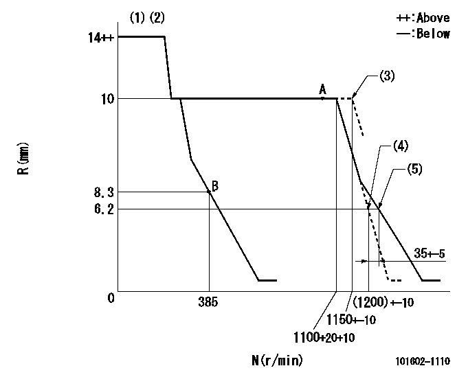
Governor adjustment

N:Pump speed
R:Rack position (mm)
(1)Notch fixed: K
(2)Deliver without the torque control spring operating.
(3)At shipping
(4)Main spring setting
(5)Set idle sub-spring
----------
K=15
----------
----------
K=15
----------
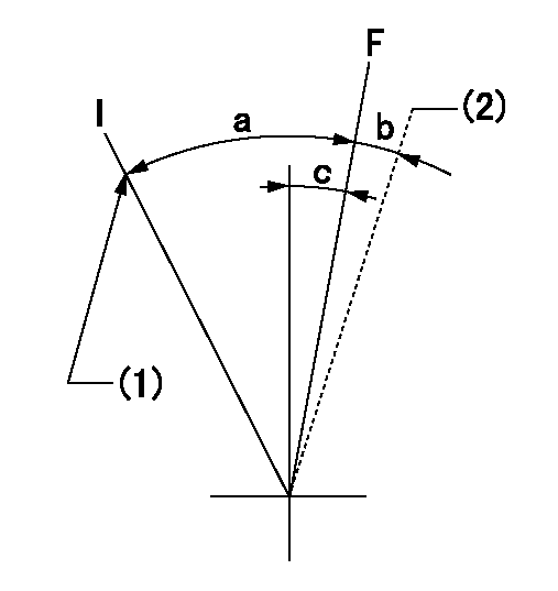
Speed control lever angle

F:Full speed
I:Idle
(1)Stopper bolt setting
(2)At shipping
----------
----------
a=23deg+-5deg b=(2deg) c=11deg+-5deg
----------
----------
a=23deg+-5deg b=(2deg) c=11deg+-5deg
Stop lever angle

N:Pump normal
S:Stop the pump.
----------
----------
a=26deg+-5deg b=53deg+-5deg
----------
----------
a=26deg+-5deg b=53deg+-5deg
Timing setting

(1)Pump vertical direction
(2)Position of coupling's tooth at No 1 cylinder's beginning of injection
(3)B.T.D.C.: aa
(4)-
----------
aa=20deg
----------
a=(3deg)
----------
aa=20deg
----------
a=(3deg)
Information:
Illustration 1 g00857824
(1) Side Panel (2) Keyboard Port (3) Mouse Port (4) Mouse (5) KeyboardConnecting A Mouse And Keyboard
Plug the mouse (4) into the mouse port (3) on the side panel (1). Plug the keyboard (5) into the keyboard port (2) on the side panel (1) .DC Power Connections
A standard three-position terminal block is provided for connecting power. Use 12 AWG stranded wire or use 14 AWG stranded wire in order to connect the terminals to a 24 VDC power supply that is stable. The 24 VDC power supply must have a minimum rating of 10 A. Observe the proper polarity. The wiring should be less than 3 meters in length. Ensure that the wires are connected correctly by using standard wiring practices. Twist the wires 1 to 3 twists per inch.Note: The ground connection must be made to an adequate earth ground. Use a short length of wire. A short length of wire eliminates the possibility of radio frequency noise and interference.
Illustration 2 g00857922
Terminal BlockNetwork Connections
The monitor accommodates CAT5 twisted pair Ethernet cables. The cables have RJ45 connectors in order to support 100Mbps network data transfer.Note: The performance of the Ethernet communications will degrade if the unit is exposed to extreme radiated noise or conducted high frequency noise. The performance of the Ethernet communications will degrade if the cables are exposed to extreme radiated noise or conducted high frequency noise. The user is responsible for properly routing the cables. The user is responsible for conditioning the input power in order to improve the reliability of communication. Note: Proper routing of the cable and proper conditioning of the power is required in order to ensure reliable Ethernet communications in industrial environments. All cables should be routed through dedicated metal conduits. Installing ferrite bead filters at cable ends may also improve reliability.
Have questions with 101602-1110?
Group cross 101602-1110 ZEXEL
Mitsubishi
101602-1110
9 400 614 716
ME070761
INJECTION-PUMP ASSEMBLY
6D15T
6D15T