Information injection-pump assembly
BOSCH
9 400 614 714
9400614714
ZEXEL
101602-1080
1016021080
MITSUBISHI
ME059690
me059690

Rating:
Service parts 101602-1080 INJECTION-PUMP ASSEMBLY:
1.
_
5.
AUTOM. ADVANCE MECHANIS
7.
COUPLING PLATE
8.
_
9.
_
11.
Nozzle and Holder
12.
Open Pre:MPa(Kqf/cm2)
21.6(220)

15.
NOZZLE SET
Cross reference number
BOSCH
9 400 614 714
9400614714
ZEXEL
101602-1080
1016021080
MITSUBISHI
ME059690
me059690
Zexel num
Bosch num
Firm num
Name
101602-1080
9 400 614 714
ME059690 MITSUBISHI
INJECTION-PUMP ASSEMBLY
6D22P K
6D22P K
Calibration Data:
Adjustment conditions
Test oil
1404 Test oil ISO4113 or {SAEJ967d}
1404 Test oil ISO4113 or {SAEJ967d}
Test oil temperature
degC
40
40
45
Nozzle and nozzle holder
105780-8140
Bosch type code
EF8511/9A
Nozzle
105780-0000
Bosch type code
DN12SD12T
Nozzle holder
105780-2080
Bosch type code
EF8511/9
Opening pressure
MPa
17.2
Opening pressure
kgf/cm2
175
Injection pipe
Outer diameter - inner diameter - length (mm) mm 6-2-600
Outer diameter - inner diameter - length (mm) mm 6-2-600
Overflow valve
132424-0620
Overflow valve opening pressure
kPa
157
123
191
Overflow valve opening pressure
kgf/cm2
1.6
1.25
1.95
Tester oil delivery pressure
kPa
157
157
157
Tester oil delivery pressure
kgf/cm2
1.6
1.6
1.6
Direction of rotation (viewed from drive side)
Right R
Right R
Injection timing adjustment
Direction of rotation (viewed from drive side)
Right R
Right R
Injection order
1-5-3-6-
2-4
Pre-stroke
mm
4.5
4.45
4.55
Beginning of injection position
Governor side NO.1
Governor side NO.1
Difference between angles 1
Cal 1-5 deg. 60 59.5 60.5
Cal 1-5 deg. 60 59.5 60.5
Difference between angles 2
Cal 1-3 deg. 120 119.5 120.5
Cal 1-3 deg. 120 119.5 120.5
Difference between angles 3
Cal 1-6 deg. 180 179.5 180.5
Cal 1-6 deg. 180 179.5 180.5
Difference between angles 4
Cyl.1-2 deg. 240 239.5 240.5
Cyl.1-2 deg. 240 239.5 240.5
Difference between angles 5
Cal 1-4 deg. 300 299.5 300.5
Cal 1-4 deg. 300 299.5 300.5
Injection quantity adjustment
Adjusting point
A
Rack position
8.9
Pump speed
r/min
900
900
900
Average injection quantity
mm3/st.
92
90
94
Max. variation between cylinders
%
0
-3
3
Basic
*
Fixing the rack
*
Injection quantity adjustment_02
Adjusting point
B
Rack position
8+-0.5
Pump speed
r/min
250
250
250
Average injection quantity
mm3/st.
17.5
14.9
20.1
Max. variation between cylinders
%
0
-14
14
Fixing the rack
*
Test data Ex:
Governor adjustment
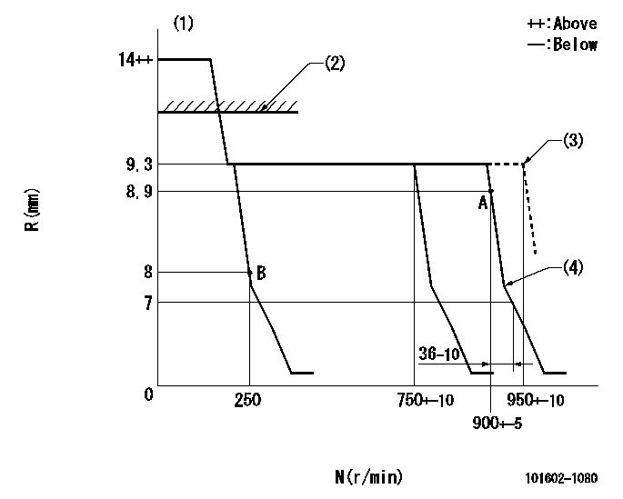
N:Pump speed
R:Rack position (mm)
(1)Target notch: K
(2)RACK LIMIT: RAL
(3)At shipping
(4)Idle sub spring setting: L1.
----------
K=16 RAL=13+1mm L1=7.5+-0.1mm
----------
----------
K=16 RAL=13+1mm L1=7.5+-0.1mm
----------
Speed control lever angle
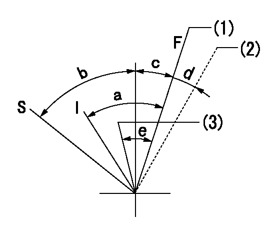
F:Full speed
I:Idle
S:Stop
(1)Pump speed = aa
(2)At shipping
(3)Pump speed = bb
----------
aa=900r/min bb=750r/min
----------
a=24deg+-5deg b=32deg+-3deg c=2deg+-5deg d=(2deg) e=5deg+-5deg
----------
aa=900r/min bb=750r/min
----------
a=24deg+-5deg b=32deg+-3deg c=2deg+-5deg d=(2deg) e=5deg+-5deg
Stop lever angle
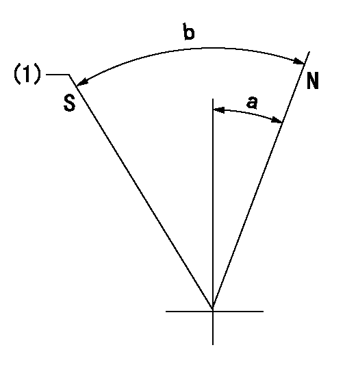
N:Pump normal
S:Stop the pump.
(1)At shipping
----------
----------
a=39deg+-5deg b=53deg+-5deg
----------
----------
a=39deg+-5deg b=53deg+-5deg
Timing setting

(1)Pump vertical direction
(2)Coupling's key groove position at No 1 cylinder's beginning of injection
(3)-
(4)-
----------
----------
a=(7deg)
----------
----------
a=(7deg)
Information:
Specifications
The following table lists the specifications for the CPU that is used on the 203-7810 Engine Monitoring Control Group and the 203-7811 Engine Monitoring Control Group.
Table 1
Item Description
Socket 7 Processor Intel Pentium MMX 233 MHz
BIOS Phoenix OEM BIOS
256 K X 8 flash EPROM (boot ROM)
Main Memory Up to 256 Mbytes DRAM (one 168 pin DIMM socket)
60 ns 3.3 V EDO / SDRAM with ECC
60 and 66 MHz bus speeds
L2 Cache Memory 512 KB pipeline burst static RAM
Chipsets Acer M1531B North Bridge
Acer M1543B South Bridge
Video Interface Chips & Technologies CHIPS 65550
2 Mbytes VGA local memory
Internal LVDS interface to indicator panel
External HD15 CRT (analog monitor) connector
Ethernet PCI 10/100 BaseT
Intel 82559 MAC
Filtered RJ-45 connector
Other CPU I/O Two RS232 serial ports ("COM1" and "COM2") (1)
Parallel port ("LPT1")
Two PS/2 ports for keyboard and mouse connections
Two USB ports
System Hardware Monitor LM78 Monitor IC mapped to IRQ5, drives diagnostics indicator
Internal temperature via DS1620 IC
User configured via BIOS
Other Features M5819 Real Time Clock chip with 256 bytes RAM
MAX705 Watchdog Timer
( 1 ) "COM2" is used by optional touchscreen interfaceSystem Hardware Monitor
The systems hardware monitor checks the following items:
2.8 V supply (CPU core)
3.3 V supply
5 V supply
12 V supply
Have questions with 101602-1080?
Group cross 101602-1080 ZEXEL
Mitsubishi
101602-1080
9 400 614 714
ME059690
INJECTION-PUMP ASSEMBLY
6D22P
6D22P