Information injection-pump assembly
BOSCH
9 400 614 712
9400614712
ZEXEL
101602-1060
1016021060
MITSUBISHI
ME059605
me059605

Rating:
Service parts 101602-1060 INJECTION-PUMP ASSEMBLY:
1.
_
5.
AUTOM. ADVANCE MECHANIS
7.
COUPLING PLATE
8.
_
9.
_
11.
Nozzle and Holder
12.
Open Pre:MPa(Kqf/cm2)
21.6(220)

15.
NOZZLE SET
Cross reference number
BOSCH
9 400 614 712
9400614712
ZEXEL
101602-1060
1016021060
MITSUBISHI
ME059605
me059605
Zexel num
Bosch num
Firm num
Name
101602-1060
9 400 614 712
ME059605 MITSUBISHI
INJECTION-PUMP ASSEMBLY
6D22P * K 14BF INJECTION PUMP ASSY PE6AD PE
6D22P * K 14BF INJECTION PUMP ASSY PE6AD PE
Calibration Data:
Adjustment conditions
Test oil
1404 Test oil ISO4113 or {SAEJ967d}
1404 Test oil ISO4113 or {SAEJ967d}
Test oil temperature
degC
40
40
45
Nozzle and nozzle holder
105780-8140
Bosch type code
EF8511/9A
Nozzle
105780-0000
Bosch type code
DN12SD12T
Nozzle holder
105780-2080
Bosch type code
EF8511/9
Opening pressure
MPa
17.2
Opening pressure
kgf/cm2
175
Injection pipe
Outer diameter - inner diameter - length (mm) mm 6-2-600
Outer diameter - inner diameter - length (mm) mm 6-2-600
Overflow valve opening pressure
kPa
157
157
157
Overflow valve opening pressure
kgf/cm2
1.6
1.6
1.6
Tester oil delivery pressure
kPa
157
157
157
Tester oil delivery pressure
kgf/cm2
1.6
1.6
1.6
Direction of rotation (viewed from drive side)
Right R
Right R
Injection timing adjustment
Direction of rotation (viewed from drive side)
Right R
Right R
Injection order
1-5-3-6-
2-4
Pre-stroke
mm
4.5
4.45
4.55
Beginning of injection position
Governor side NO.1
Governor side NO.1
Difference between angles 1
Cal 1-5 deg. 60 59.5 60.5
Cal 1-5 deg. 60 59.5 60.5
Difference between angles 2
Cal 1-3 deg. 120 119.5 120.5
Cal 1-3 deg. 120 119.5 120.5
Difference between angles 3
Cal 1-6 deg. 180 179.5 180.5
Cal 1-6 deg. 180 179.5 180.5
Difference between angles 4
Cyl.1-2 deg. 240 239.5 240.5
Cyl.1-2 deg. 240 239.5 240.5
Difference between angles 5
Cal 1-4 deg. 300 299.5 300.5
Cal 1-4 deg. 300 299.5 300.5
Injection quantity adjustment
Adjusting point
A
Rack position
8.9
Pump speed
r/min
900
900
900
Average injection quantity
mm3/st.
92
90
94
Max. variation between cylinders
%
0
-3
3
Basic
*
Fixing the rack
*
Injection quantity adjustment_02
Adjusting point
B
Rack position
8+-0.5
Pump speed
r/min
250
250
250
Average injection quantity
mm3/st.
17.5
14.9
20.1
Max. variation between cylinders
%
0
-14
14
Fixing the rack
*
Test data Ex:
Governor adjustment
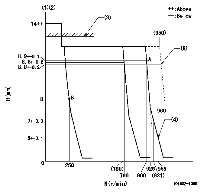
N:Pump speed
R:Rack position (mm)
(1)Target notch: K
(2)Tolerance for racks not indicated: +-0.05mm.
(3)RACK LIMIT: RAL
(4)Set idle sub-spring
(5)At shipping
----------
K=18 RAL=13+0.1mm
----------
----------
K=18 RAL=13+0.1mm
----------
Speed control lever angle
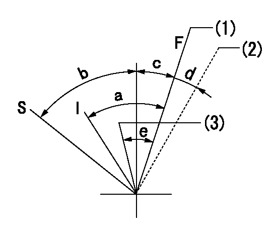
F:Full speed
I:Idle
S:Stop
(1)Pump speed = aa
(2)At shipping
(3)Pump speed = bb
----------
aa=900r/min bb=760r/min
----------
a=24deg+-5deg b=32deg+-3deg c=2deg+-5deg d=(2deg) e=5deg+-5deg
----------
aa=900r/min bb=760r/min
----------
a=24deg+-5deg b=32deg+-3deg c=2deg+-5deg d=(2deg) e=5deg+-5deg
Stop lever angle
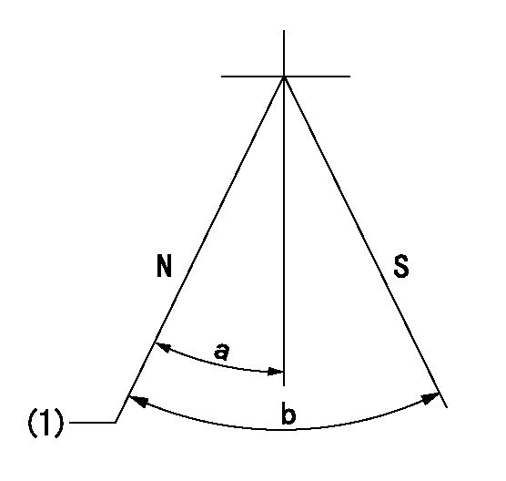
N:Pump normal
S:Stop the pump.
(1)Normal
----------
----------
a=19deg+-5deg b=53deg+-5deg
----------
----------
a=19deg+-5deg b=53deg+-5deg
Information:
Monitor
Illustration 1 g00856663
(1) Display (2) Indicators (3) Bezel With Stud Mounting (Standard NEMA Type 4)Connectors
Illustration 2 g00856664
(4) I/O Card (5) CPU Card (6) Shared PCI/ISA Expansion Slot (7) Serial Port 1 (DB9) (8) Backlight Dimming Control (9) PCI Slot (10) Video Port (HD-15) (11) Ethernet Connection (RJ45) (12) Parallel Port (DB25) (13) 2 USB Ports (14) 3.5" Internal Hard Drive (15) PS/2 Keyboard Connector (Mini DIN) (16) 3.5" Floppy Drive (17) PS/2 Mouse Connector (Mini DIN) (18) Cooling Fan and Filter (Bottom)Indicators
The following tables describe the indicators on the monitor. The labels for the indicators are symbols.
Illustration 3 g00856666
Diagnostic Indicator
Table 1
Position Color Description
Left Red Diagnostics The diagnostic indicator shows when one of the following conditions exists:Over Temperature - The temperature inside of the monitor enclosure is above the defined threshold.Fan Sensor - The system fan is not operating within the defined thresholds.Voltage - The voltages are not within the specifications.Refer to Troubleshooting, "Diagnostic Indicator Is On - Troubleshoot" for information on resolving diagnostic conditions.
Illustration 4 g00856667
Hard Drive Access Indicator
Table 2
Position Color Description
Center Green Hard Drive Access
Illustration 5 g00856668
Power On Indicator
Table 3
Position Color Description
Right Green Power On Backlight Dimming Control
Use the backlight dimming control (8) in order to vary the screen lighting for optimum viewing.Turn the control clockwise in order to increase the brightness of the display. Turn the control counterclockwise in order to dim the display backlight.
Have questions with 101602-1060?
Group cross 101602-1060 ZEXEL
Mitsubishi
101602-1060
9 400 614 712
ME059605
INJECTION-PUMP ASSEMBLY
6D22P
6D22P