Information injection-pump assembly
BOSCH
F 01G 09U 034
f01g09u034
ZEXEL
101602-1050
1016021050
MITSUBISHI
ME059628
me059628
Rating:
Service parts 101602-1050 INJECTION-PUMP ASSEMBLY:
1.
_
5.
AUTOM. ADVANCE MECHANIS
7.
COUPLING PLATE
8.
_
9.
_
11.
Nozzle and Holder
12.
Open Pre:MPa(Kqf/cm2)
21.6(220)

15.
NOZZLE SET
Cross reference number
BOSCH
F 01G 09U 034
f01g09u034
ZEXEL
101602-1050
1016021050
MITSUBISHI
ME059628
me059628
Zexel num
Bosch num
Firm num
Name
101602-1050
F 01G 09U 034
ME059628 MITSUBISHI
INJECTION-PUMP ASSEMBLY
6D22C * K
6D22C * K
Calibration Data:
Adjustment conditions
Test oil
1404 Test oil ISO4113 or {SAEJ967d}
1404 Test oil ISO4113 or {SAEJ967d}
Test oil temperature
degC
40
40
45
Nozzle and nozzle holder
105780-8140
Bosch type code
EF8511/9A
Nozzle
105780-0000
Bosch type code
DN12SD12T
Nozzle holder
105780-2080
Bosch type code
EF8511/9
Opening pressure
MPa
17.2
Opening pressure
kgf/cm2
175
Injection pipe
Outer diameter - inner diameter - length (mm) mm 6-2-600
Outer diameter - inner diameter - length (mm) mm 6-2-600
Overflow valve
131424-4620
Overflow valve opening pressure
kPa
255
221
289
Overflow valve opening pressure
kgf/cm2
2.6
2.25
2.95
Tester oil delivery pressure
kPa
157
157
157
Tester oil delivery pressure
kgf/cm2
1.6
1.6
1.6
Direction of rotation (viewed from drive side)
Right R
Right R
Injection timing adjustment
Direction of rotation (viewed from drive side)
Right R
Right R
Injection order
1-5-3-6-
2-4
Pre-stroke
mm
4.5
4.45
4.55
Beginning of injection position
Governor side NO.1
Governor side NO.1
Difference between angles 1
Cal 1-5 deg. 60 59.5 60.5
Cal 1-5 deg. 60 59.5 60.5
Difference between angles 2
Cal 1-3 deg. 120 119.5 120.5
Cal 1-3 deg. 120 119.5 120.5
Difference between angles 3
Cal 1-6 deg. 180 179.5 180.5
Cal 1-6 deg. 180 179.5 180.5
Difference between angles 4
Cyl.1-2 deg. 240 239.5 240.5
Cyl.1-2 deg. 240 239.5 240.5
Difference between angles 5
Cal 1-4 deg. 300 299.5 300.5
Cal 1-4 deg. 300 299.5 300.5
Injection quantity adjustment
Adjusting point
A
Rack position
9.2
Pump speed
r/min
900
900
900
Average injection quantity
mm3/st.
101
99
103
Max. variation between cylinders
%
0
-3
3
Basic
*
Fixing the lever
*
Injection quantity adjustment_02
Adjusting point
B
Rack position
7.6+-0.5
Pump speed
r/min
250
250
250
Average injection quantity
mm3/st.
17.5
14.9
20.1
Max. variation between cylinders
%
0
-15
15
Fixing the rack
*
Test data Ex:
Governor adjustment
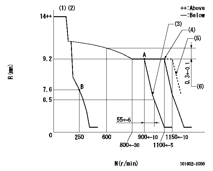
N:Pump speed
R:Rack position (mm)
(1)Target notch: K
(2)The torque control spring must does not have a set force.
(3)Idle sub spring setting: L1.
(4)Torque spring does not operate.
(5)At shipping
(6)Rack difference between N = N1 and N = N2
----------
K=15 L1=7.3+-0.1mm N1=900r/min N2=600r/min
----------
----------
K=15 L1=7.3+-0.1mm N1=900r/min N2=600r/min
----------
Speed control lever angle
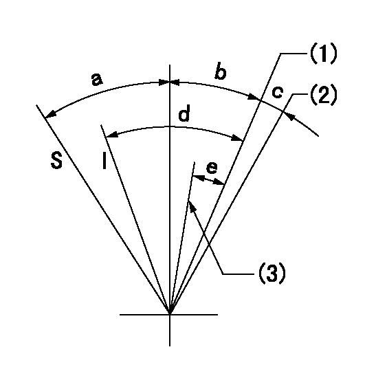
I:Idle
S:Stop
(1)Pump speed = aa
(2)At shipping
(3)Pump speed = bb
----------
aa=1100r/min bb=900r/min
----------
a=32deg+-3deg b=10deg+-5deg c=(2deg) d=25deg+-5deg e=7deg+-5deg
----------
aa=1100r/min bb=900r/min
----------
a=32deg+-3deg b=10deg+-5deg c=(2deg) d=25deg+-5deg e=7deg+-5deg
Stop lever angle

N:Pump normal
S:Stop the pump.
----------
----------
a=19deg+-5deg b=53deg+-5deg
----------
----------
a=19deg+-5deg b=53deg+-5deg
Timing setting

(1)Pump vertical direction
(2)Coupling's key groove position at No 1 cylinder's beginning of injection
(3)-
(4)-
----------
----------
a=(7deg)
----------
----------
a=(7deg)
Information:
Remove the single tie bolt (6) that is located in the top left corner of the pump by using Tooling (B). Refer to Illustration 7. Only remove the single tie bolt (6). Removing more bolts will result in damage to the pump.
Illustration 2 g01132938
(1) HEUI pump (2) Fuel transfer pump (4) Drive gear (5) 227-5904 O-Ring Seal (6) Tie Bolt (7) Bolts for the fuel transfer pump (8) Tie Bolts (9) Location for service bolt (12) 185-3241 O-Ring Seal
Replace tie bolt (6) with the temporary service bolt (9) that is provided in the service kit.Note: The service bolt that is provided in the kit has an undersized bolt head. The service bolt prevents the body of the HEUI pump from separating during service. Do not remove the service bolt until the fuel transfer pump has been completely reinstalled.
Tighten the service bolt (9) to 10 N m (7.4 lb ft) by using Tooling (C) .Note: Do not place an excessive torque on the service bolt. The aluminum housing of the pump could be damaged.
After installing the service bolt (9) in the top left location, remove the three bolts (7) that fasten the fuel transfer pump to the HEUI pump by using Tooling (A) .
Proceed by removing the remaining three tie bolts (8) by using Tooling (B) .
Separate the fuel transfer pump from the HEUI pump. Refer to Illustration 3.
Illustration 3 g01132944
(1) HEUI pump (2) Fuel transfer pump (9) Service bolt (10) Seals (11) SealInstalling the Fuel Transfer Pump onto the HEUI Pump
Install the two new 239-2402 Seals (10) on the back face of the HEUI pump (1). Refer to Illustration 4.
Illustration 4 g01077898
(1) HEUI pump (10) 239-2402 Seals
Install a new 179-8128 Seal (11) on the fuel transfer pump (2). Refer to Illustration 5. Use 1U-6396 O-Ring Assembly Compound in order to hold the seal in place during assembly. Ensure that the seal is completely seated.
Illustration 5 g01132957
(2) Fuel transfer pump (11) 179-8128 Seal
Do not remove the service bolt. Position the fuel transfer pump on the HEUI pump. Be sure to properly align the drive tang on the fuel transfer pump with the drive slot on the HEUI pump.Note: Align the drive tang of the fuel transfer pump so that the flat end is vertical. Refer to Illustration 5. Align the drive slot in the HEUI pump to a similar vertical orientation by using a flat head screwdriver. Refer to Illustration 6.
Illustration 6 g01132969
Note: Once the fuel transfer pump has been placed onto the HEUI pump, ensure that the face of the fuel transfer pump is flush with the face of the HEUI pump. If the pump faces are not flush, verify the alignment of the drive tang.
Install the three mounting bolts (7) for the fuel transfer pump (2). Tighten
Have questions with 101602-1050?
Group cross 101602-1050 ZEXEL
Mitsubishi
101602-1050
F 01G 09U 034
ME059628
INJECTION-PUMP ASSEMBLY
6D22C
6D22C