Information injection-pump assembly
ZEXEL
101602-0930
1016020930
ISUZU
1156012240
1156012240
Rating:
Cross reference number
ZEXEL
101602-0930
1016020930
ISUZU
1156012240
1156012240
Zexel num
Bosch num
Firm num
Name
Calibration Data:
Adjustment conditions
Test oil
1404 Test oil ISO4113 or {SAEJ967d}
1404 Test oil ISO4113 or {SAEJ967d}
Test oil temperature
degC
40
40
45
Nozzle and nozzle holder
105780-8140
Bosch type code
EF8511/9A
Nozzle
105780-0000
Bosch type code
DN12SD12T
Nozzle holder
105780-2080
Bosch type code
EF8511/9
Opening pressure
MPa
17.2
Opening pressure
kgf/cm2
175
Injection pipe
Outer diameter - inner diameter - length (mm) mm 6-2-600
Outer diameter - inner diameter - length (mm) mm 6-2-600
Overflow valve
132424-0620
Overflow valve opening pressure
kPa
157
123
191
Overflow valve opening pressure
kgf/cm2
1.6
1.25
1.95
Tester oil delivery pressure
kPa
157
157
157
Tester oil delivery pressure
kgf/cm2
1.6
1.6
1.6
Direction of rotation (viewed from drive side)
Right R
Right R
Injection timing adjustment
Direction of rotation (viewed from drive side)
Right R
Right R
Injection order
1-5-3-6-
2-4
Pre-stroke
mm
3.4
3.35
3.45
Beginning of injection position
Drive side NO.1
Drive side NO.1
Difference between angles 1
Cal 1-5 deg. 60 59.5 60.5
Cal 1-5 deg. 60 59.5 60.5
Difference between angles 2
Cal 1-3 deg. 120 119.5 120.5
Cal 1-3 deg. 120 119.5 120.5
Difference between angles 3
Cal 1-6 deg. 180 179.5 180.5
Cal 1-6 deg. 180 179.5 180.5
Difference between angles 4
Cyl.1-2 deg. 240 239.5 240.5
Cyl.1-2 deg. 240 239.5 240.5
Difference between angles 5
Cal 1-4 deg. 300 299.5 300.5
Cal 1-4 deg. 300 299.5 300.5
Injection quantity adjustment
Adjusting point
A
Rack position
8.5
Pump speed
r/min
800
800
800
Average injection quantity
mm3/st.
73
71.5
74.5
Max. variation between cylinders
%
0
-2.5
2.5
Basic
*
Fixing the lever
*
Injection quantity adjustment_02
Adjusting point
B
Rack position
5.6+-0.5
Pump speed
r/min
400
400
400
Average injection quantity
mm3/st.
9.4
8.1
10.7
Max. variation between cylinders
%
0
-14
14
Fixing the rack
*
Remarks
Adjust only variation between cylinders; adjust governor according to governor specifications.
Adjust only variation between cylinders; adjust governor according to governor specifications.
Test data Ex:
Governor adjustment
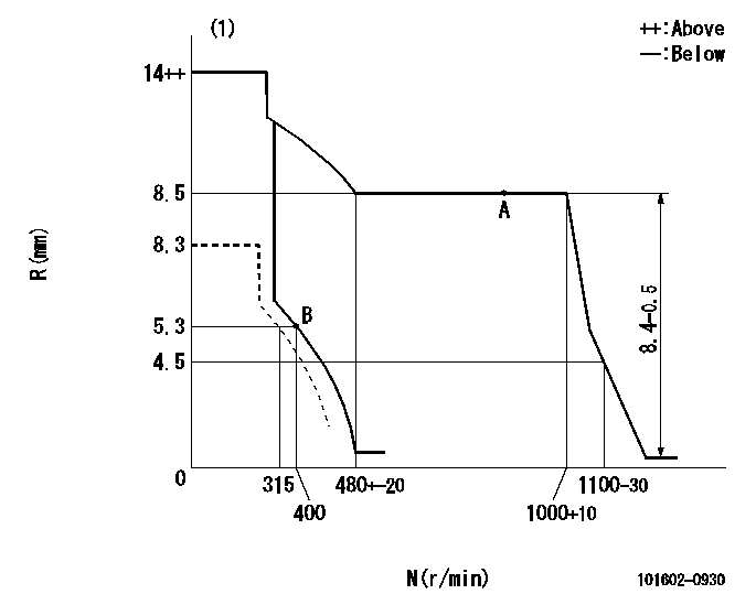
N:Pump speed
R:Rack position (mm)
(1)Target notch: K
----------
K=8
----------
----------
K=8
----------
Speed control lever angle
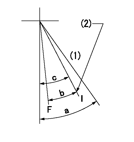
F:Full speed
I:Idle
(1)Cancel dead point
(2)Stopper bolt setting
----------
----------
a=20deg+-3deg b=17deg+-5deg c=18deg+-1deg
----------
----------
a=20deg+-3deg b=17deg+-5deg c=18deg+-1deg
Stop lever angle
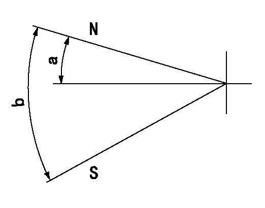
N:Pump normal
S:Stop the pump.
----------
----------
a=12deg+-5deg b=46deg+-5deg
----------
----------
a=12deg+-5deg b=46deg+-5deg
0000001501 LEVER
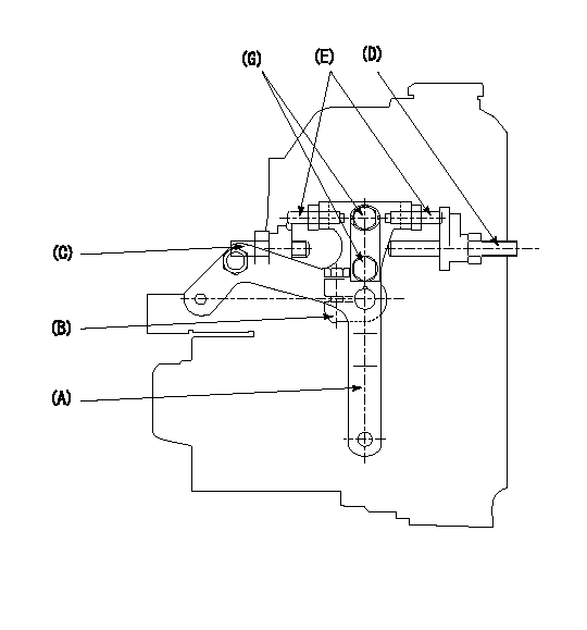
1. Variable lever adjustment
(1)Fix lever (B) in the beginning of speed increase position using bolts (C) and (D).
(2)Fix using the bolt E so that the lever A is aa.
(3)Lock using bolt (G).
(4)After completing idle adjustment, loosen the full side stopper bolt (D).
(5)Move the lever (A) in the full speed direction.
(6)Fix bolt (D) at full speed position.
(7)Finally, measure the lever angle and set the idle stopper bolt (C) stop position.
----------
aa=18deg+-1deg
----------
----------
aa=18deg+-1deg
----------
Timing setting
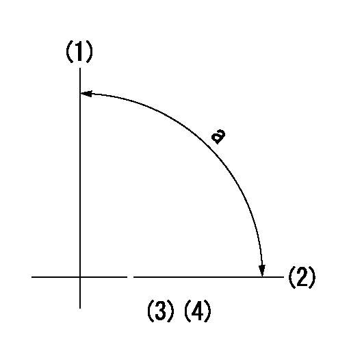
(1)Pump vertical direction
(2)Position of gear mark 'CC' at No 1 cylinder's beginning of injection
(3)B.T.D.C.: aa
(4)-
----------
aa=18deg
----------
a=(90deg)
----------
aa=18deg
----------
a=(90deg)
Information:
Table 1
M5X COMMUNICATION TROUBLESHOOTING
Problem Possible Explanation Action Required
CCM shows error codes E02 and E08 when receiving data from the PC and will not communicate. 1. There is a protocol error.
2. The data is not in ASCII format.
3. An incorrect checksum was sent.
4. Baud rate of the CCM and PC not matched. Correct the message being sent to the CCM
RS-232 receive lights are not lighted, and the CCM will not communicate with the PC even though no error codes are appearing. Hardware connection between the PC and CCM is corrupted or disconnected. Using the CCM PC software, connect to the CCM and determine if the connection to the PC is valid.
Cannot log into the CCM Connection problem exists or using the wrong M5X protocol for logging in. Use a read request (PID $F0 $12) to verify that the PC is available to communicate with the CCM. If a valid response is returned, proceed to log in as described in the Logging in section of this manual. If the password has been forgotten, call the CCM Help Desk.
Cannot get data from the electronic controller. 1. The electronic controller specified is not available.
2. The logged in security level is not high enough to support the request.
3. The electronic controller does not support the PID. 1. Verify that the electronic controller and the CCM are connected on the same data link.
2. Verify that the logged in security level is high enough to support the request.
3. Verify that the electronic controller supports the PID being requested.
Multiple responses are being generated from a single electronic controller Multiple electronic controllers have the same MID. Program the engine number of the electronic controller. Refer to the CCM/Data Link Guidelines section and Programming the Engine Number section in this manual.
An entire broadcast list is not returned. 1. The electronic controller specified is not available.
2. The electronic controller does not support any one of the PID's.
3. The PID contains greater than two bytes of data. Refer to the CCM Customized System section, IID 10 and IID 13 in this manual
A broadcast list update rate is too slow or inconsistent. 1. Too many parameters are being requested.
2. RS-232 baud rate is slow. 1. Verify that the RS-232 and modem baud rates are at least 9600 baud. CCM can not broadcast more than 40 parameters per second. Use IID 13, Byte 7 to slow the update rate for stable parameters such as hour meter, atmospheric pressure, temperature, diagnostics, etc. Use a faster rate for more dynamic parameters such as engine speed, oil pressure, etc. Refer to the RS-232 Communication Protocol for Customized Systems section in this manual for further information.
2. Increase the RS-232 baud rate.