Information injection-pump assembly
ZEXEL
101602-0850
1016020850
ISUZU
1156011661
1156011661
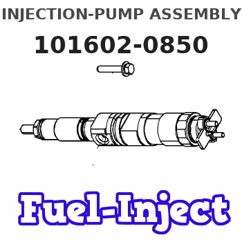
Rating:
Service parts 101602-0850 INJECTION-PUMP ASSEMBLY:
1.
_
5.
AUTOM. ADVANCE MECHANIS
7.
COUPLING PLATE
8.
_
9.
_
11.
Nozzle and Holder
5-15300-103-2
12.
Open Pre:MPa(Kqf/cm2)
14.7{150}
15.
NOZZLE SET
Cross reference number
ZEXEL
101602-0850
1016020850
ISUZU
1156011661
1156011661
Zexel num
Bosch num
Firm num
Name
101602-0850
1156011661 ISUZU
INJECTION-PUMP ASSEMBLY
6BD1 * K 14BE PE6A PE
6BD1 * K 14BE PE6A PE
Calibration Data:
Adjustment conditions
Test oil
1404 Test oil ISO4113 or {SAEJ967d}
1404 Test oil ISO4113 or {SAEJ967d}
Test oil temperature
degC
40
40
45
Nozzle and nozzle holder
105780-8140
Bosch type code
EF8511/9A
Nozzle
105780-0000
Bosch type code
DN12SD12T
Nozzle holder
105780-2080
Bosch type code
EF8511/9
Opening pressure
MPa
17.2
Opening pressure
kgf/cm2
175
Injection pipe
Outer diameter - inner diameter - length (mm) mm 6-2-600
Outer diameter - inner diameter - length (mm) mm 6-2-600
Tester oil delivery pressure
kPa
157
157
157
Tester oil delivery pressure
kgf/cm2
1.6
1.6
1.6
Direction of rotation (viewed from drive side)
Right R
Right R
Injection timing adjustment
Direction of rotation (viewed from drive side)
Right R
Right R
Injection order
1-5-3-6-
2-4
Pre-stroke
mm
3.6
3.55
3.65
Beginning of injection position
Drive side NO.1
Drive side NO.1
Difference between angles 1
Cal 1-5 deg. 60 59.5 60.5
Cal 1-5 deg. 60 59.5 60.5
Difference between angles 2
Cal 1-3 deg. 120 119.5 120.5
Cal 1-3 deg. 120 119.5 120.5
Difference between angles 3
Cal 1-6 deg. 180 179.5 180.5
Cal 1-6 deg. 180 179.5 180.5
Difference between angles 4
Cyl.1-2 deg. 240 239.5 240.5
Cyl.1-2 deg. 240 239.5 240.5
Difference between angles 5
Cal 1-4 deg. 300 299.5 300.5
Cal 1-4 deg. 300 299.5 300.5
Injection quantity adjustment
Adjusting point
A
Rack position
7.3
Pump speed
r/min
800
800
800
Average injection quantity
mm3/st.
63.8
62.8
64.8
Max. variation between cylinders
%
0
-2
2
Basic
*
Fixing the lever
*
Injection quantity adjustment_02
Adjusting point
B
Rack position
7.2
Pump speed
r/min
1000
1000
1000
Average injection quantity
mm3/st.
66.4
64.4
68.4
Max. variation between cylinders
%
0
-4
4
Fixing the lever
*
Injection quantity adjustment_03
Adjusting point
C
Rack position
4.5+-0.5
Pump speed
r/min
350
350
350
Average injection quantity
mm3/st.
9.4
8.1
10.7
Max. variation between cylinders
%
0
-14
14
Fixing the rack
*
Remarks
Adjust only variation between cylinders; adjust governor according to governor specifications.
Adjust only variation between cylinders; adjust governor according to governor specifications.
Test data Ex:
Governor adjustment
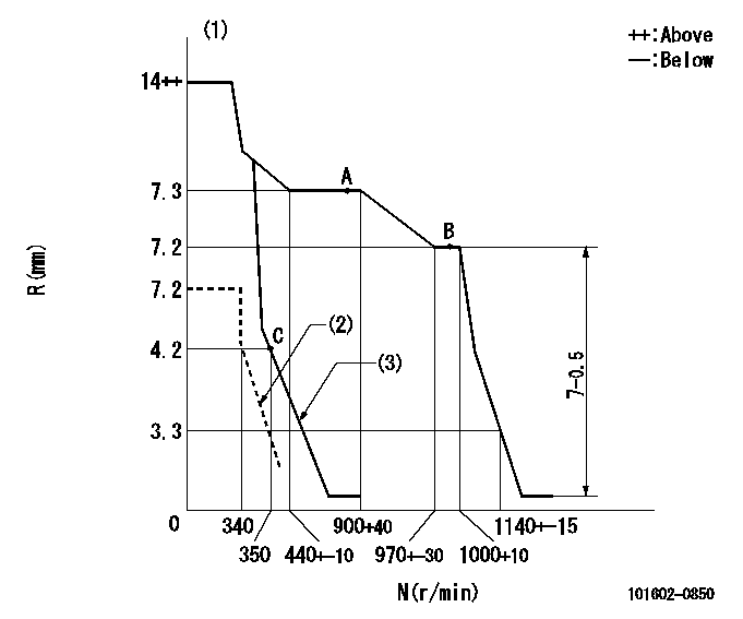
N:Pump speed
R:Rack position (mm)
(1)Target notch: K
(2)Set idle sub-spring
(3)Main spring setting
----------
K=12
----------
----------
K=12
----------
Speed control lever angle
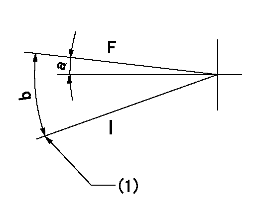
F:Full speed
I:Idle
(1)Stopper bolt setting
----------
----------
a=5deg+-5deg b=18deg+-5deg
----------
----------
a=5deg+-5deg b=18deg+-5deg
Stop lever angle
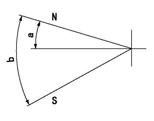
N:Pump normal
S:Stop the pump.
----------
----------
a=12deg+-5deg b=46deg+-5deg
----------
----------
a=12deg+-5deg b=46deg+-5deg
Information:
Illustration 1 g00656709
(1) Error code (2) Activity on CAT Data Link (3) First digit of error code (4) The CCM is transmitting on RS 232C. (5) Second digit of error code (6) The CCM is receiving data on the RS 232C.The values E, 0, and 0 indicate an error code of 00. The code E00 means that no faults are present, and the CCM is in normal operating mode. The complete list of error codes are in the Operation and Maintenance Manual, "Troubleshooting" section. The periods on the display will flash when information is transmitted on the CAT Data Link. The periods on the display will flash when information is transmitted on the RS-232C port. No period indicates that no activity is taking place.Note: Units with the part number 117-6170 Customer Communication Module will display the faults that have been logged. Each fault will be displayed for 2 seconds in 60 second intervals. This flashing fault log will not appear for any other version of CCM. The fault log can be cleared by using the PC software for the CCM.CCM Power Up Display
The CCM display will perform a lamp test (8.8.8.). The parameters for communication protocol (n81 9600 E00) will be displayed next. An example of the power up sequence is given below:
Table 1
8.8.8. n81 9600 E00
8.8.8. All of the segments are turned on for a two second lamp test.
n81
n
8
1 No parity (default value)
Eight data bits (default value)
One stop bit (default value)
9600 Rate of Communication (default value)
E00 Error Code
No faults are present. The values for communication can be changed by using a host device or by using the PC software for the CCM. Refer to "Caterpillar CCM PC For Windows: Getting Started Manual". The values for communication must match the values for the modems (if used) and the values for the host device.
Have questions with 101602-0850?
Group cross 101602-0850 ZEXEL
Isuzu
101602-0850
1156011661
INJECTION-PUMP ASSEMBLY
6BD1
6BD1
