Information injection-pump assembly
BOSCH
9 400 614 706
9400614706
ZEXEL
101602-0830
1016020830
ISUZU
1156011101
1156011101
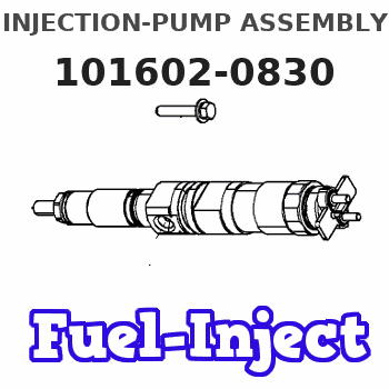
Rating:
Service parts 101602-0830 INJECTION-PUMP ASSEMBLY:
1.
_
5.
AUTOM. ADVANCE MECHANIS
7.
COUPLING PLATE
8.
_
9.
_
11.
Nozzle and Holder
1-15300-105-2
12.
Open Pre:MPa(Kqf/cm2)
18.1{185}
15.
NOZZLE SET
Cross reference number
BOSCH
9 400 614 706
9400614706
ZEXEL
101602-0830
1016020830
ISUZU
1156011101
1156011101
Zexel num
Bosch num
Firm num
Name
101602-0830
9 400 614 706
1156011101 ISUZU
INJECTION-PUMP ASSEMBLY
6BD1T K 14BE INJECTION PUMP ASSY PE6A PE
6BD1T K 14BE INJECTION PUMP ASSY PE6A PE
Calibration Data:
Adjustment conditions
Test oil
1404 Test oil ISO4113 or {SAEJ967d}
1404 Test oil ISO4113 or {SAEJ967d}
Test oil temperature
degC
40
40
45
Nozzle and nozzle holder
105780-8140
Bosch type code
EF8511/9A
Nozzle
105780-0000
Bosch type code
DN12SD12T
Nozzle holder
105780-2080
Bosch type code
EF8511/9
Opening pressure
MPa
17.2
Opening pressure
kgf/cm2
175
Injection pipe
Outer diameter - inner diameter - length (mm) mm 6-2-600
Outer diameter - inner diameter - length (mm) mm 6-2-600
Overflow valve opening pressure
kPa
157
123
191
Overflow valve opening pressure
kgf/cm2
1.6
1.25
1.95
Tester oil delivery pressure
kPa
157
157
157
Tester oil delivery pressure
kgf/cm2
1.6
1.6
1.6
Direction of rotation (viewed from drive side)
Right R
Right R
Injection timing adjustment
Direction of rotation (viewed from drive side)
Right R
Right R
Injection order
1-5-3-6-
2-4
Pre-stroke
mm
3.4
3.35
3.45
Beginning of injection position
Drive side NO.1
Drive side NO.1
Difference between angles 1
Cal 1-5 deg. 60 59.5 60.5
Cal 1-5 deg. 60 59.5 60.5
Difference between angles 2
Cal 1-3 deg. 120 119.5 120.5
Cal 1-3 deg. 120 119.5 120.5
Difference between angles 3
Cal 1-6 deg. 180 179.5 180.5
Cal 1-6 deg. 180 179.5 180.5
Difference between angles 4
Cyl.1-2 deg. 240 239.5 240.5
Cyl.1-2 deg. 240 239.5 240.5
Difference between angles 5
Cal 1-4 deg. 300 299.5 300.5
Cal 1-4 deg. 300 299.5 300.5
Injection quantity adjustment
Adjusting point
A
Rack position
8.4
Pump speed
r/min
1250
1250
1250
Average injection quantity
mm3/st.
81.4
79.9
82.9
Max. variation between cylinders
%
0
-2.5
2.5
Basic
*
Fixing the lever
*
Boost pressure
kPa
69.3
69.3
Boost pressure
mmHg
520
520
Injection quantity adjustment_02
Adjusting point
C
Rack position
7.8
Pump speed
r/min
500
500
500
Average injection quantity
mm3/st.
48.4
46.4
50.4
Max. variation between cylinders
%
0
-4
4
Fixing the lever
*
Boost pressure
kPa
0
0
0
Boost pressure
mmHg
0
0
0
Injection quantity adjustment_03
Adjusting point
D
Rack position
5.2+-0.5
Pump speed
r/min
325
325
325
Average injection quantity
mm3/st.
12.1
10.8
13.4
Max. variation between cylinders
%
0
-14
14
Fixing the rack
*
Boost pressure
kPa
0
0
0
Boost pressure
mmHg
0
0
0
Boost compensator adjustment
Pump speed
r/min
800
800
800
Rack position
7.8
Boost pressure
kPa
17.3
14.6
20
Boost pressure
mmHg
130
110
150
Boost compensator adjustment_02
Pump speed
r/min
800
800
800
Rack position
8.6
Boost pressure
kPa
56
49.3
62.7
Boost pressure
mmHg
420
370
470
Test data Ex:
Governor adjustment
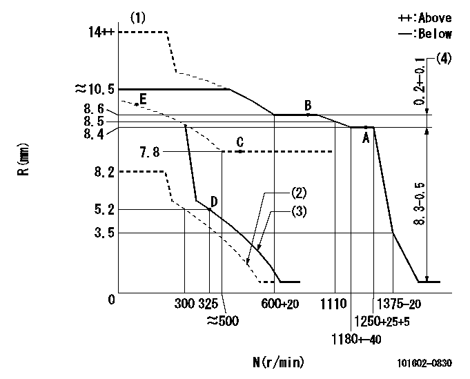
N:Pump speed
R:Rack position (mm)
(1)Target notch: K
(2)Set idle sub-spring
(3)Main spring setting
(4)Rack difference between N = N1 and N = N2
----------
K=11 N1=1250r/min N2=800r/min
----------
----------
K=11 N1=1250r/min N2=800r/min
----------
Speed control lever angle
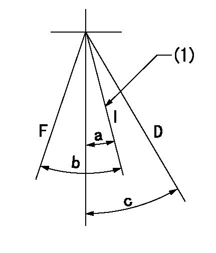
F:Full speed
I:Idle
D:Dead point
(1)Stopper bolt setting
----------
----------
a=17deg+-1deg b=28deg+-5deg c=20deg+-3deg
----------
----------
a=17deg+-1deg b=28deg+-5deg c=20deg+-3deg
Stop lever angle
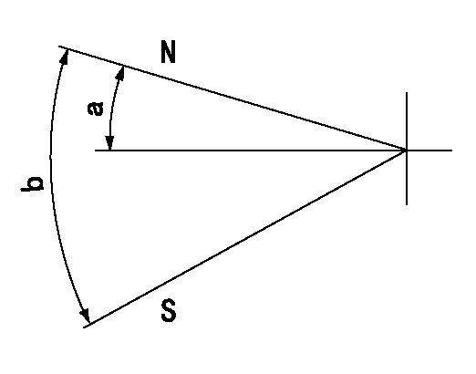
N:Pump normal
S:Stop the pump.
----------
----------
a=12deg+-5deg b=46deg+-5deg
----------
----------
a=12deg+-5deg b=46deg+-5deg
0000001501 LEVER
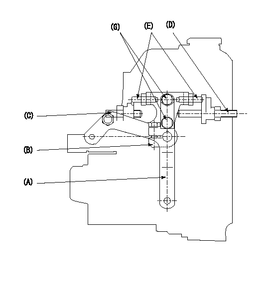
1. Variable lever adjustment
(1)Fix lever (B) in the beginning of speed increase position using bolts (C) and (D).
(2)Temporarily fix the lever (A) at the dead point and measure the lever angle .
(3)Fix the lever (A) at the idle lever angle position using the bolt (E).
(4)Lock using bolt (G).
(5)After completing idle adjustment, loosen the full side stopper bolt (D).
(6)Move the lever (A) in the full speed direction.
(7)Fix bolt (D) at full speed position.
(8)Finally, measure the lever angle and set the idle stopper bolt (C) stop position.
----------
----------
----------
----------
Information:
zz is the number of bytes in the message after this byte. zz does not include the checksum. This value will change depending on the data that is associated with the IID.Checksum Calculation
The checksum is an important part of the M5X message. By using the checksum, the integrity of the message is determined. The second to last byte of every IID is the checksum, which is followed by an ASCII carriage return ($0D). The checksum is a 2's complement value of the summation of all the data bytes in the message. The message is a good message if all the bytes and the checksum add to zero (0).The following message is an example.5000240400580082AE<cr>The checksum for this message is AE. Although the message is sent in ASCII, the checksum must be calculated by using the hexadecimal value.
Table 3
Byte ASCII Value Hexadecimal Value
50 $35 $30 $50
00 $30 $30 $00
24 $32 $34 $24
04 $30 $34 $04
00 $30 $30 $00
58 $35 $38 $58
00 $30 $30 $00
82 $38 $32 $82
Total $152
Truncated to LSB $52
2's Compement $41 $45 $AE
Total $100
Truncated to LSB $00 CCM Heartbeat
You should check the connection to the CCM before you log in to the CCM. You should also check the connection (heartbeat) to the CCM during normal operation from time to time. The recommended PID is $F0 $12. Use PID $F0 $12 to read the current Security Level at a regular interval as a heartbeat. If the CCM does not answer to the read request, then there is a problem with the connection. This PID will also monitor the Security Level, which may have been changed.Security Levels
Every PID has an associated security level (0, 1, 2, or 3) within the CCM. A user within a particular security level may use PID's in that level or lower levels. PID's cannot be accessed by the user in levels higher than the password allows. For example, a user at security level 2 can access level 2, 1, and 0, but not level 3.The answering modem will be hung up if the password is not entered (sets the security level) within one minute. Specifically, if DCD is held low by the PC, and the security level is at 0 for more than one minute, DTR will be toggled by the CCM (answering modem hung up). Also, if the RS-232C cable is disconnected for more than five seconds, DTR will be toggled, and the security level will be set to 0.When power is removed from the CCM, the security level will be changed to 2, if the CCM was operating at security level 3.The following chart defines the PID's within each security level
Have questions with 101602-0830?
Group cross 101602-0830 ZEXEL
Isuzu
101602-0830
9 400 614 706
1156011101
INJECTION-PUMP ASSEMBLY
6BD1T
6BD1T
