Information injection-pump assembly
BOSCH
9 400 614 704
9400614704
ZEXEL
101602-0700
1016020700
ISUZU
1156010333
1156010333

Rating:
Service parts 101602-0700 INJECTION-PUMP ASSEMBLY:
1.
_
5.
AUTOM. ADVANCE MECHANIS
6.
COUPLING PLATE
8.
_
9.
_
11.
Nozzle and Holder
5-15300-089-1
12.
Open Pre:MPa(Kqf/cm2)
18.1{185}

15.
NOZZLE SET
Cross reference number
BOSCH
9 400 614 704
9400614704
ZEXEL
101602-0700
1016020700
ISUZU
1156010333
1156010333
Zexel num
Bosch num
Firm num
Name
Calibration Data:
Adjustment conditions
Test oil
1404 Test oil ISO4113 or {SAEJ967d}
1404 Test oil ISO4113 or {SAEJ967d}
Test oil temperature
degC
40
40
45
Nozzle and nozzle holder
105780-8140
Bosch type code
EF8511/9A
Nozzle
105780-0000
Bosch type code
DN12SD12T
Nozzle holder
105780-2080
Bosch type code
EF8511/9
Opening pressure
MPa
17.2
Opening pressure
kgf/cm2
175
Injection pipe
Outer diameter - inner diameter - length (mm) mm 6-2-600
Outer diameter - inner diameter - length (mm) mm 6-2-600
Tester oil delivery pressure
kPa
157
157
157
Tester oil delivery pressure
kgf/cm2
1.6
1.6
1.6
Direction of rotation (viewed from drive side)
Right R
Right R
Injection timing adjustment
Direction of rotation (viewed from drive side)
Right R
Right R
Injection order
1-5-3-6-
2-4
Pre-stroke
mm
2.4
2.35
2.45
Beginning of injection position
Drive side NO.1
Drive side NO.1
Difference between angles 1
Cal 1-5 deg. 60 59.5 60.5
Cal 1-5 deg. 60 59.5 60.5
Difference between angles 2
Cal 1-3 deg. 120 119.5 120.5
Cal 1-3 deg. 120 119.5 120.5
Difference between angles 3
Cal 1-6 deg. 180 179.5 180.5
Cal 1-6 deg. 180 179.5 180.5
Difference between angles 4
Cyl.1-2 deg. 240 239.5 240.5
Cyl.1-2 deg. 240 239.5 240.5
Difference between angles 5
Cal 1-4 deg. 300 299.5 300.5
Cal 1-4 deg. 300 299.5 300.5
Injection quantity adjustment
Adjusting point
A
Rack position
8.9
Pump speed
r/min
750
750
750
Average injection quantity
mm3/st.
33.2
31.7
34.7
Max. variation between cylinders
%
0
-2.5
2.5
Basic
*
Fixing the lever
*
Injection quantity adjustment_02
Adjusting point
B
Rack position
8.4
Pump speed
r/min
1000
1000
1000
Average injection quantity
mm3/st.
32.8
31
34.6
Max. variation between cylinders
%
0
-4
4
Fixing the lever
*
Injection quantity adjustment_03
Adjusting point
C
Rack position
7.7+-0.5
Pump speed
r/min
325
325
325
Average injection quantity
mm3/st.
12.4
11.1
13.7
Max. variation between cylinders
%
0
-14
14
Fixing the rack
*
Test data Ex:
Governor adjustment
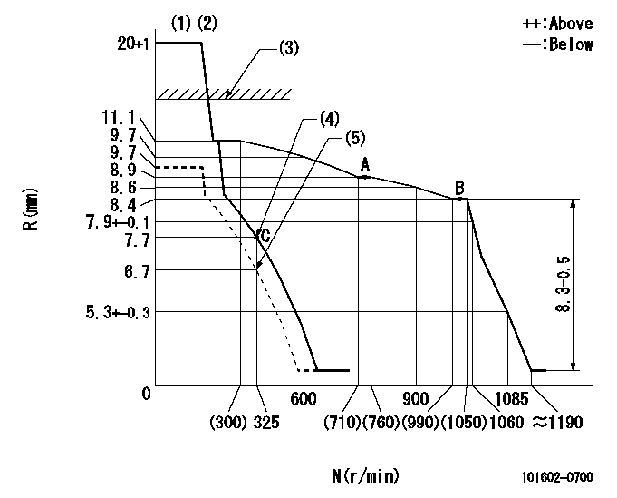
N:Pump speed
R:Rack position (mm)
(1)Target notch: K
(2)Tolerance for racks not indicated: +-0.05mm.
(3)RACK CAP: R1
(4)Main spring setting
(5)Set idle sub-spring
----------
K=16 R1=(17.5)mm
----------
----------
K=16 R1=(17.5)mm
----------
Speed control lever angle

F:Full speed
I:Idle
(1)Stopper bolt setting
----------
----------
a=13.5deg+-5deg b=32deg+-5deg
----------
----------
a=13.5deg+-5deg b=32deg+-5deg
Stop lever angle

N:Pump normal
S:Stop the pump.
----------
----------
a=12deg+-5deg b=46deg+-5deg
----------
----------
a=12deg+-5deg b=46deg+-5deg
Timing setting

(1)Pump vertical direction
(2)Position of gear mark 'CC' at No 1 cylinder's beginning of injection
(3)B.T.D.C.: aa
(4)-
----------
aa=20deg
----------
a=(90deg)
----------
aa=20deg
----------
a=(90deg)
Information:
Control System PLC Outputs Hardwired to Relay Logic (Not Available to Customer)
Table 10
ISA TAG # PLC CARD # OUTPUT DESCRIPTION PLC REG ASSIGN SIGNAL TYPE ALARM SHUT DOWN TRIP / ACTIVATION CONDITION COMMENTS
YC-001 PLC07 Air Start to Engine O:7.0/03 DIGITAL Remote Start Only
YC-002 PLC07 Fuel Shutoff Signal to Engine O:7.0/00 DIGITAL X Shutdown or Fuel Off RFCR Relay
YC-015 PLC07 Air Shutoff Signal to Engine O:7.0/02 DIGITAL Overspeed and E-Stop ASOS Solenoid
YC-003 PLC07 Engine Prelube Signal to Engine O:7.0/01 DIGITAL >
9 kPa (1.3 psi) RPR Relay
YC-008 PLC07 Engine Protection System Override Relay On I:2.0/07 DIGITAL ROVR Relay - Override Shutdowns
YC-009 PLC07 Summary Group Alarm Relay Active O:7.0/05 DIGITAL X Any Alarm RSA Relay
YC-010 PLC07 Summary group Shutdown Signal O:7.0/07 DIGITAL X Protective Shutdown Energizes REFR Relay on Protective Shutdown
LY-001 PLC02 Jacket Water Detection Relay I:2.0/12 DIGITAL X RJWDA Relay Control System Lights and Meters
Table 11
ISA TAG # PLC CARD # OUTPUT DESCRIPTION PLC REG ASSIGN SIGNAL TYPE ALARM SHUT DOWN TRIP / ACTIVATION CONDITION COMMENTS
SI-004 Engine Speed Tachometer FREQ Mag Piclup Driven
SS1-001 Engine Hour Meter DIGITAL
PI-023 Starting Air Pressure Meter OHMS Resistive Sensor
YAL-009 PLC07 Summary Alarm Light O:7.0/06 DIGITAL X Any Alarm
YAL-010 PLC07 Summary Shutdown Light O:7.0/07 DIGITAL X Protective Shutdown
YAL-015 PLC07 PLC Failure O:7.0/15 DIGITAL X No Signal to RPLCFA RPLCFA De-energized on PLC Failure
PIL-008 Engine Prelubed DIGITAL >
9 kPa (1.3 psi)