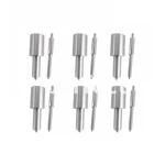
Information injection-pump assembly
ZEXEL
101602-0660
1016020660
ISUZU
1156009391
1156009391

Rating:
Service parts 101602-0660 INJECTION-PUMP ASSEMBLY:
1.
_
5.
AUTOM. ADVANCE MECHANIS
8.
_
9.
_
11.
Nozzle and Holder
5-15300-103-2
12.
Open Pre:MPa(Kqf/cm2)
14.7{150}
15.
NOZZLE SET
Include in #1:
101602-0660
as INJECTION-PUMP ASSEMBLY
Include in #2:
104762-4020
as _
Cross reference number
Zexel num
Bosch num
Firm num
Name
101602-0660
1156009391 ISUZU
INJECTION-PUMP ASSEMBLY
6BB1 * K 14BE PE6A PE
6BB1 * K 14BE PE6A PE
Information:
The results of the preceding procedure are in the following list:
The output corresponds to the desired pressure range. Stop.
The output does not correspond to the desired pressure range. Proceed to 3.
Calibrate the transducer. This assumes that the transducer is mounted on the engine.
Turn the isolation valve on the transducer mounting. This isolates the transducer from the engine. An arrow on the valve indicates the direction of flow. See illustration 2.
Apply a pressure that is equal to 4 mA to the transducer. See table 1. See the pressure port connection in illustration 2.
Monitor the ammeter. Adjust the zero dial until the ammeter reads 4mA. See the location of the zero dial that is in illustration 1.
Apply the pressure that is equal to 20mA to the transducer. See table 1. See the pressure port connection in illustration 2.Note: The full range of pressure may not be available. Use partial pressure. Use the highest possible pressure. This will yield the best accuracy. See table 1.
Monitor the ammeter. Adjust the zero dial until the ammeter reads 20mA. See the location of the zero dial that is in illustration 1.
Apply the pressure that is equal to 4mA to the transducer. Verify that the ammeter displays 4mA.The results of the preceding procedure are in the following list:
The output corresponds to the desired pressure range. The transducer is calibrated. Stop.
The output does not correspond to the desired pressure range. Proceed to 4.
Reapply the pressure.
Apply the pressure that is equal to 4mA to the transducer. See table 1. See the pressure port connection in illustration 2.
Monitor the ammeter. Adjust the zero dial until the ammeter reads 4mA. See the location of the zero dial that is in illustration 1.
Apply the pressure that is equal to 20mA to the transducer. See table 1. See the pressure port connection in illustration 2.Note: The full range of pressure may not be available. Use partial pressure. Use the highest possible pressure. This will yield the best accuracy. See table 1.
Monitor the ammeter. Adjust the zero dial until the ammeter reads 20mA. See the location of the zero dial that is in illustration 1.
Apply the pressure that is equal to 4mA to the transducer. Verify that the ammeter displays 4mA.The results of the preceding procedure are in the following list:Note: Repeat the procedure several times in order to properly calibrate the transducer. Continue until the 4mA signal is correct and the 20mA signal is correct.
The output corresponds to the desired pressure range. The transducer is calibrated. Stop.
The output does not correspond to the desired pressure range. Replace the transducer. Verify that the repair resolves the problem. Stop.
Have questions with 101602-0660?
Group cross 101602-0660 ZEXEL
Isuzu
101602-0660
1156009391
INJECTION-PUMP ASSEMBLY
6BB1
6BB1
