Information injection-pump assembly
ZEXEL
101602-0510
1016020510
ISUZU
1156008263
1156008263
Rating:
Cross reference number
ZEXEL
101602-0510
1016020510
ISUZU
1156008263
1156008263
Zexel num
Bosch num
Firm num
Name
Calibration Data:
Adjustment conditions
Test oil
1404 Test oil ISO4113 or {SAEJ967d}
1404 Test oil ISO4113 or {SAEJ967d}
Test oil temperature
degC
40
40
45
Nozzle and nozzle holder
105780-8140
Bosch type code
EF8511/9A
Nozzle
105780-0000
Bosch type code
DN12SD12T
Nozzle holder
105780-2080
Bosch type code
EF8511/9
Opening pressure
MPa
17.2
Opening pressure
kgf/cm2
175
Injection pipe
Outer diameter - inner diameter - length (mm) mm 6-2-600
Outer diameter - inner diameter - length (mm) mm 6-2-600
Overflow valve opening pressure
kPa
157
123
191
Overflow valve opening pressure
kgf/cm2
1.6
1.25
1.95
Tester oil delivery pressure
kPa
157
157
157
Tester oil delivery pressure
kgf/cm2
1.6
1.6
1.6
Direction of rotation (viewed from drive side)
Right R
Right R
Injection timing adjustment
Direction of rotation (viewed from drive side)
Right R
Right R
Injection order
1-5-3-6-
2-4
Pre-stroke
mm
2.4
2.35
2.45
Beginning of injection position
Drive side NO.1
Drive side NO.1
Difference between angles 1
Cal 1-5 deg. 60 59.5 60.5
Cal 1-5 deg. 60 59.5 60.5
Difference between angles 2
Cal 1-3 deg. 120 119.5 120.5
Cal 1-3 deg. 120 119.5 120.5
Difference between angles 3
Cal 1-6 deg. 180 179.5 180.5
Cal 1-6 deg. 180 179.5 180.5
Difference between angles 4
Cyl.1-2 deg. 240 239.5 240.5
Cyl.1-2 deg. 240 239.5 240.5
Difference between angles 5
Cal 1-4 deg. 300 299.5 300.5
Cal 1-4 deg. 300 299.5 300.5
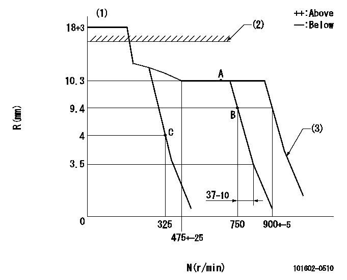
Injection quantity adjustment
Adjusting point
A
Rack position
10.3
Pump speed
r/min
725
725
725
Average injection quantity
mm3/st.
59
57.2
60.8
Max. variation between cylinders
%
0
-4
4
Fixing the lever
*
Injection quantity adjustment_02
Adjusting point
B
Rack position
9.4
Pump speed
r/min
750
750
750
Average injection quantity
mm3/st.
54.5
53
56
Max. variation between cylinders
%
0
-2.5
2.5
Basic
*
Fixing the rack
*
Injection quantity adjustment_03
Adjusting point
C
Rack position
4.5+-0.5
Pump speed
r/min
325
325
325
Average injection quantity
mm3/st.
9.4
8.1
10.7
Max. variation between cylinders
%
0
-14
14
Fixing the rack
*
Remarks
Adjust only variation between cylinders; adjust governor according to governor specifications.
Adjust only variation between cylinders; adjust governor according to governor specifications.
Test data Ex:
Governor adjustment
N:Pump speed
R:Rack position (mm)
(1)Target notch: K
(2)RACK CAP: R1
(3)Idle sub spring setting: L1.
----------
K=5 R1=(17.5)mm L1=3.5-0.5mm
----------
----------
K=5 R1=(17.5)mm L1=3.5-0.5mm
----------
Speed control lever angle
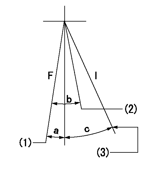
F:Full speed
I:Idle
(1)Speed set at aa (setting at shipping)
(2)Set the pump speed at bb.
(3)Stopper bolt setting
----------
aa=900r/min bb=750r/min
----------
a=1.5deg+-5deg b=4.5deg+-3deg c=17.5deg+-5deg
----------
aa=900r/min bb=750r/min
----------
a=1.5deg+-5deg b=4.5deg+-3deg c=17.5deg+-5deg
Stop lever angle

N:Pump normal
S:Stop the pump.
----------
----------
a=19deg+-5deg b=53deg+-5deg
----------
----------
a=19deg+-5deg b=53deg+-5deg
Timing setting

(1)Pump vertical direction
(2)Position of gear mark 'CC' at No 1 cylinder's beginning of injection
(3)B.T.D.C.: aa
(4)-
----------
aa=20deg
----------
a=(90deg)
----------
aa=20deg
----------
a=(90deg)
Information:
Introduction
The problem that is identified below does not have a permanent solution. Until a permanent solution is known, use the solution that is listed below.Problem
A significant amount of HEUI pumps and injectors have been returned, but no cause of failure can be determined.Solution
Diagnostic procedures have been updated and have been incorporated into the following publications:
Special Instruction, REHS3819, "Procedure for Troubleshooting and Cleaning the Oil Rail System for the Hydraulic Electronic Unit Injector (HEUI)"
Troubleshooting, "Injection Actuation Pressure - Test"Note: These publications have been translated into Mandarin and Spanish.In addition, a new troubleshooting checklist is included with all service repair for HUEI pumps and HEUI injectors. The checklist is a summary of the diagnostic procedure steps to be confirmed before a suspect component is replaced. The checklist must be completed and returned with the suspect components in order to aid engineering to determine the cause of failure.Following the instructions step-by-step is critical in order to diagnose the failed component correctly. Do not skip steps in the procedures. Skipping steps in the procedure will lead to incorrect diagnosis of the problem.