Information injection-pump assembly
ZEXEL
101602-0460
1016020460
ISUZU
5156011283
5156011283
Rating:
Service parts 101602-0460 INJECTION-PUMP ASSEMBLY:
1.
_

5.
AUTOM. ADVANCE MECHANIS
6.
COUPLING PLATE
8.
_
9.
_
11.
Nozzle and Holder
5-15300-089-1
12.
Open Pre:MPa(Kqf/cm2)
18.1{185}

15.
NOZZLE SET
Cross reference number
ZEXEL
101602-0460
1016020460
ISUZU
5156011283
5156011283
Zexel num
Bosch num
Firm num
Name
Calibration Data:
Adjustment conditions
Test oil
1404 Test oil ISO4113 or {SAEJ967d}
1404 Test oil ISO4113 or {SAEJ967d}
Test oil temperature
degC
40
40
45
Nozzle and nozzle holder
105780-8140
Bosch type code
EF8511/9A
Nozzle
105780-0000
Bosch type code
DN12SD12T
Nozzle holder
105780-2080
Bosch type code
EF8511/9
Opening pressure
MPa
17.2
Opening pressure
kgf/cm2
175
Injection pipe
Outer diameter - inner diameter - length (mm) mm 6-2-600
Outer diameter - inner diameter - length (mm) mm 6-2-600
Tester oil delivery pressure
kPa
157
157
157
Tester oil delivery pressure
kgf/cm2
1.6
1.6
1.6
Direction of rotation (viewed from drive side)
Right R
Right R
Injection timing adjustment
Direction of rotation (viewed from drive side)
Right R
Right R
Injection order
1-5-3-6-
2-4
Pre-stroke
mm
3.6
3.55
3.65
Beginning of injection position
Drive side NO.1
Drive side NO.1
Difference between angles 1
Cal 1-5 deg. 60 59.5 60.5
Cal 1-5 deg. 60 59.5 60.5
Difference between angles 2
Cal 1-3 deg. 120 119.5 120.5
Cal 1-3 deg. 120 119.5 120.5
Difference between angles 3
Cal 1-6 deg. 180 179.5 180.5
Cal 1-6 deg. 180 179.5 180.5
Difference between angles 4
Cyl.1-2 deg. 240 239.5 240.5
Cyl.1-2 deg. 240 239.5 240.5
Difference between angles 5
Cal 1-4 deg. 300 299.5 300.5
Cal 1-4 deg. 300 299.5 300.5
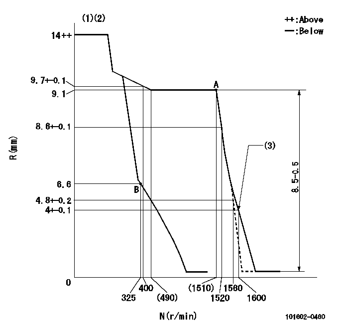
Injection quantity adjustment
Adjusting point
A
Rack position
9.1
Pump speed
r/min
1500
1500
1500
Average injection quantity
mm3/st.
64.5
63
66
Max. variation between cylinders
%
0
-2
2
Basic
*
Fixing the rack
*
Injection quantity adjustment_02
Adjusting point
B
Rack position
6.6+-0.5
Pump speed
r/min
325
325
325
Average injection quantity
mm3/st.
9.2
7.9
10.5
Max. variation between cylinders
%
0
-14
14
Fixing the rack
*
Test data Ex:
Governor adjustment
N:Pump speed
R:Rack position (mm)
(1)Target notch: K
(2)Tolerance for racks not indicated: +-0.05mm.
(3)Set idle sub-spring
----------
K=5
----------
----------
K=5
----------
Speed control lever angle
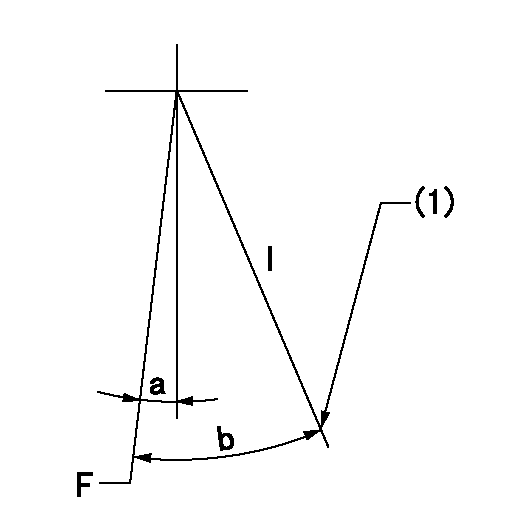
F:Full speed
I:Idle
(1)Stopper bolt setting
----------
----------
a=5.5deg+-5deg b=29deg+-5deg
----------
----------
a=5.5deg+-5deg b=29deg+-5deg
Stop lever angle

N:Pump normal
S:Stop the pump.
----------
----------
a=(4.5deg) b=(53deg)
----------
----------
a=(4.5deg) b=(53deg)
Timing setting

(1)Pump vertical direction
(2)Position of gear mark 'CC' at No 1 cylinder's beginning of injection
(3)B.T.D.C.: aa
(4)-
----------
aa=20deg
----------
a=(90deg)
----------
aa=20deg
----------
a=(90deg)
Information:
Shutdowns
A shutdown secures the fuel and a shutdown secures the air to the engine. A fuel shutoff solenoid may be located in the fuel actuator. The fuel shutoff solenoid is energized. The injector is driven to the off position. This secures the fuel.The air shutoff solenoid secures the air. When this solenoid is activated compressed air flows to the air damper. The air releases a pin. When the pin is released, a spring closes the air damper. This secures the combustion air supply from the turbochargers to the aftercooler.Note: The air damper must be MANUALLY reset before the engine can be restarted. The Marine Engine Control Panel must also be reset with the "RESET" switch before the MMS will allow starting. The panel may not be reset until the engine has stopped rotating. Determine the cause of the shutdown and correct the problem prior to engine operation.
Table 2
Shutdowns of the Marine Monitoring System
Description Sensor Location
Group Part Number (1) Set Point Source of the Alarm
Pressure
Low Oil Pressure 142-5916 or 146-9438 Block 1
105 kPa (15 psi) @LS
260 kPa (38) @HS Low Speed Oil Contactor or High Speed Oil Contactor, or the Lube Oil Filter Outlet Pressure Transducer
High Crankcase Pressure 147-2369 In-line 142-5919 Vee
1 kPa (.15 psi) Crankcase pressure contactor
Temperature
High Jacket Water Outlet Temperature 142-5916 or 146-9438 Block 4
109 °C (228 °F) Jacket Water Contactor or Optional Transducer
Miscellaneous
Oil Mist Detector Various Contact Closure Oil Mist Detector - Not in all engines
Overspeed 146-5522, 146-5523, 146-5524, 146-5525 113% of Rated Speed Engine Speed Switch and MMS
Metal Particle Detection Basic Engine Metal Particles in Oil Plus 5 Seconds Metal Particle Detector
( 1 ) The group part numbers are provided for reference only. For individual part numbers see Reference Information, "Reference Parts Information".Low Speed - The engine speed is below 75% of the rated engine speed.High Speed - The engine speed is above 75% of the rated engine speed.The "Sensor Failure Alarm" Screen
The "Sensor Failure Alarm" screen is displayed when unexpected signals are received by the PLC. The alarm monitors sensors which can produce alarms or shutdowns.
Table 3
Sensor Failure Alarms for the Marine Monitoring System
Description Sensor Location
Group Part Number (1) Set Point Source of the Alarm
RTD/PT 100 Failures Various
< -50 °C (-58 °F) or
> 150 °C (302 °F) Lube oil, After Cooler/Oil Cooler, Jacket Water, and Inlet Manifold Temperatures
Thermocouples Various
< -50 °C (-58 °F) or
> 700 °C (1292 °F) Individual Cylinder, Pre-Turbine, and Stack Thermocouples
4-20mA Transducers Various < 3.5 mA or > 20.15 mA Engine Speed Transducer, Lube Oil and Fuel pressure transducers
Contactors Various No signal