Information injection-pump assembly
ZEXEL
101602-0110
1016020110
ISUZU
5156006201
5156006201

Rating:
Cross reference number
ZEXEL
101602-0110
1016020110
ISUZU
5156006201
5156006201
Zexel num
Bosch num
Firm num
Name
Calibration Data:
Adjustment conditions
Test oil
1404 Test oil ISO4113 or {SAEJ967d}
1404 Test oil ISO4113 or {SAEJ967d}
Test oil temperature
degC
40
40
45
Nozzle and nozzle holder
105101-4970
Nozzle
105015-3600
Bosch type code
9 432 610 405
Nozzle holder
105031-3470
Opening pressure
MPa
18.1
Opening pressure
kgf/cm2
185
Injection pipe
Outer diameter - inner diameter - length (mm) mm 6-2-380
Outer diameter - inner diameter - length (mm) mm 6-2-380
Overflow valve
132424-0620
Overflow valve opening pressure
kPa
157
123
191
Overflow valve opening pressure
kgf/cm2
1.6
1.25
1.95
Tester oil delivery pressure
kPa
157
157
157
Tester oil delivery pressure
kgf/cm2
1.6
1.6
1.6
Direction of rotation (viewed from drive side)
Right R
Right R
Injection timing adjustment
Direction of rotation (viewed from drive side)
Right R
Right R
Injection order
1-5-3-6-
2-4
Pre-stroke
mm
3.5
3.45
3.55
Beginning of injection position
Drive side NO.1
Drive side NO.1
Difference between angles 1
Cal 1-5 deg. 60 59.5 60.5
Cal 1-5 deg. 60 59.5 60.5
Difference between angles 2
Cal 1-3 deg. 120 119.5 120.5
Cal 1-3 deg. 120 119.5 120.5
Difference between angles 3
Cal 1-6 deg. 180 179.5 180.5
Cal 1-6 deg. 180 179.5 180.5
Difference between angles 4
Cyl.1-2 deg. 240 239.5 240.5
Cyl.1-2 deg. 240 239.5 240.5
Difference between angles 5
Cal 1-4 deg. 300 299.5 300.5
Cal 1-4 deg. 300 299.5 300.5
Injection quantity adjustment
Adjusting point
A
Rack position
8.8
Pump speed
r/min
1350
1350
1350
Average injection quantity
mm3/st.
65
63.5
66.5
Max. variation between cylinders
%
0
-2.5
2.5
Basic
*
Fixing the rack
*
Injection quantity adjustment_02
Adjusting point
B
Rack position
6.1+-0.5
Pump speed
r/min
300
300
300
Average injection quantity
mm3/st.
9.4
8.1
10.7
Max. variation between cylinders
%
0
-14
14
Fixing the rack
*
Test data Ex:
Governor adjustment
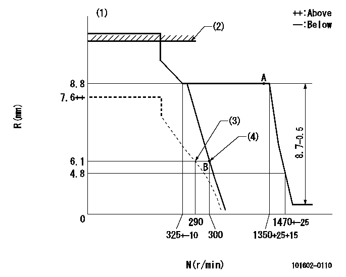
N:Pump speed
R:Rack position (mm)
(1)Target notch: K
(2)At rack cap installation: R1
(3)Set idle sub-spring
(4)Main spring setting
----------
K=9 R1=(17.5)mm
----------
----------
K=9 R1=(17.5)mm
----------
Speed control lever angle

F:Full speed
I:Idle
(1)Stopper bolt setting
----------
----------
a=10deg+-5deg b=34deg+-5deg
----------
----------
a=10deg+-5deg b=34deg+-5deg
Information:
Illustration 8 g00778880
This is an illustration of the 154-8016 Fuel Injector Seals . (14) Metal Seal (15) 133-3715 Backup Ring (16) 150-4105 Backup Ring (17) 9X-7557 O-Ring Seal (18) 148-2903 O-Ring Seal (19) 149-5240 Backup Ring (20) 109-3207 O-Ring Seal
Illustration 9 g00638512
(A) 149-2955 Seal Protector
Illustration 10 g00638506
(B) 149-2956 Seal Installer
The correct procedures and tooling specifications must always be used. Failure to follow any of the procedures may result in damage, malfunction, or possible engine failure.
Note: Install the upper seal pack first. Then install the middle seal pack. Finally, install the bottom O-Ring Seal.
Both the 149-2955 Seal Protector (A) and the 149-2956 Seal Installer (B) should be used when you are installing the upper high pressure seals.Note: New seals should be installed after each removal of the injector from the engine.
Lubricate the O-Ring seals and the sleeve bore of the injector sparingly with clean engine oil.Note: Proper installation of the injector is very important. Damage to the upper high pressure seals can cause excessive oil leakage under the valve cover. This may cause the engine not to start due to a low actuation pressure. Damage to the lower high pressure seals may allow high pressure oil to leak into the fuel supply passage. This will result in excessive oil consumption.
Illustration 11 g00621566
(X) 8T-2396 Bolts . (Y) 159-0288 Deflector . Note: Some of these engines were built without the 159-0288 Deflector . During the installation of the unit injectors, the deflectors should be installed. Six 159-0288 Deflectors and six 8T-2396 Bolts are required for each engine. These new deflectors and bolts replace the former 6V-8653 Bolts .
Illustration 12 g00294210
Illustration 13 g00312124
(C) 152-1057 Fuel Injector Installer
Carefully install the injector into the injector bore. If access permits you to seat the injector, push the injector straight down on top of the injector's solenoid by hand until the injector is firmly seated in the injector bore. Pushing hard enough to compress the injector's seals may be difficult. If the injector can not be seated by hand, use a 152-1057 Fuel Injector Installer (C). Note: Do NOT pry on the top of the injector with another tool. Do NOT strike the injector with a hammer. Damage to the injector will result. Damage to the injector that is due to improper installation is not a warrantable failure.
Illustration 14 g00778888
(2) Wiring Harness Connection (3) Clamp (10) Shoulder Bolt (11) Socket Head BoltNote: Do not use the shoulder bolt and the socket head bolt in order to seat the injector. If a side load is placed on the bolts, the bolts may fail.
After the injector is seated, position the clamp (2) and tighten the Shoulder Bolt (10) to a torque of 6 N m (50 lb in). Then tighten the Socket Head Bolt (11) to a torque of 12 N m (9 lb ft).
Insert the harness connectors (2) back into the injectors' solenoids. Ensure that the clips are snapped back into