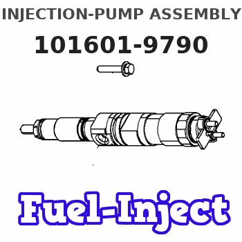
Information injection-pump assembly
ZEXEL
101601-9790
1016019790
Rating:
Cross reference number
ZEXEL
101601-9790
1016019790
Zexel num
Bosch num
Firm num
Name
Calibration Data:
Adjustment conditions
Test oil
1404 Test oil ISO4113 or {SAEJ967d}
1404 Test oil ISO4113 or {SAEJ967d}
Test oil temperature
degC
40
40
45
Nozzle and nozzle holder
105780-8140
Bosch type code
EF8511/9A
Nozzle
105780-0000
Bosch type code
DN12SD12T
Nozzle holder
105780-2080
Bosch type code
EF8511/9
Opening pressure
MPa
17.2
Opening pressure
kgf/cm2
175
Injection pipe
Outer diameter - inner diameter - length (mm) mm 6-2-600
Outer diameter - inner diameter - length (mm) mm 6-2-600
Overflow valve
131424-5520
Overflow valve opening pressure
kPa
255
221
289
Overflow valve opening pressure
kgf/cm2
2.6
2.25
2.95
Tester oil delivery pressure
kPa
157
157
157
Tester oil delivery pressure
kgf/cm2
1.6
1.6
1.6
Direction of rotation (viewed from drive side)
Left L
Left L
Injection timing adjustment
Direction of rotation (viewed from drive side)
Left L
Left L
Injection order
1-5-3-6-
2-4
Pre-stroke
mm
3.3
3.25
3.35
Beginning of injection position
Governor side NO.1
Governor side NO.1
Difference between angles 1
Cal 1-5 deg. 60 59.5 60.5
Cal 1-5 deg. 60 59.5 60.5
Difference between angles 2
Cal 1-3 deg. 120 119.5 120.5
Cal 1-3 deg. 120 119.5 120.5
Difference between angles 3
Cal 1-6 deg. 180 179.5 180.5
Cal 1-6 deg. 180 179.5 180.5
Difference between angles 4
Cyl.1-2 deg. 240 239.5 240.5
Cyl.1-2 deg. 240 239.5 240.5
Difference between angles 5
Cal 1-4 deg. 300 299.5 300.5
Cal 1-4 deg. 300 299.5 300.5
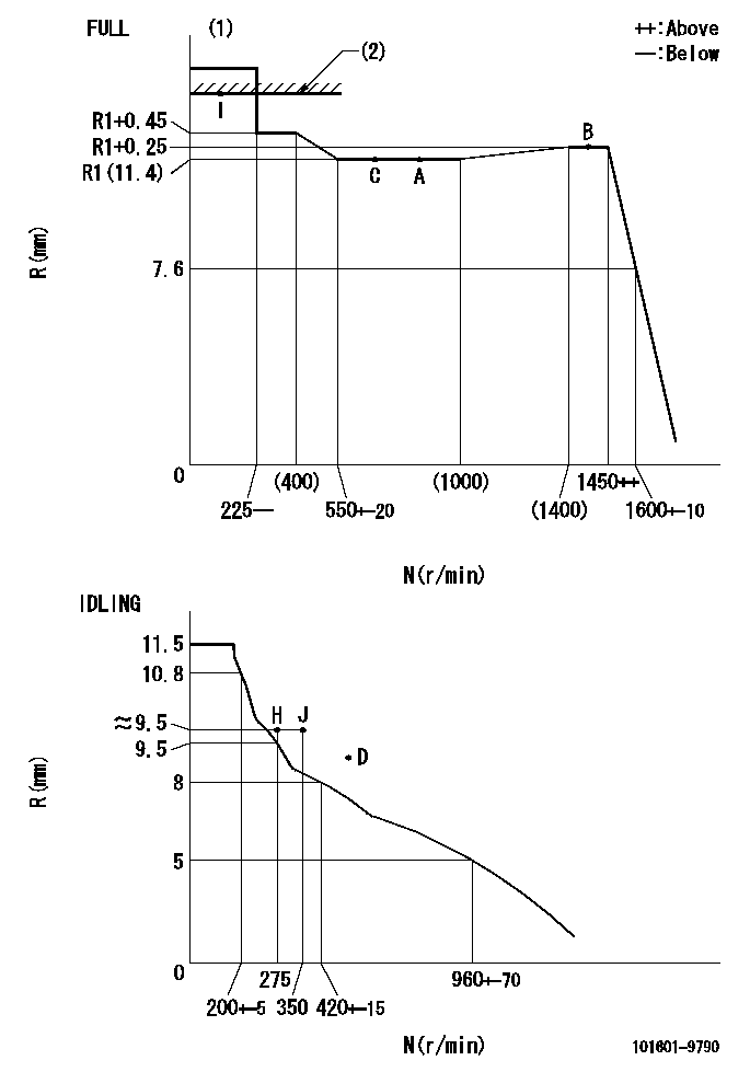
Injection quantity adjustment
Adjusting point
-
Rack position
11.4
Pump speed
r/min
700
700
700
Each cylinder's injection qty
mm3/st.
54.5
52
57
Basic
*
Fixing the rack
*
Standard for adjustment of the maximum variation between cylinders
*
Injection quantity adjustment_02
Adjusting point
D
Rack position
8.7+-0.5
Pump speed
r/min
500
500
500
Each cylinder's injection qty
mm3/st.
7.6
5.9
9.3
Fixing the rack
*
Standard for adjustment of the maximum variation between cylinders
*
Injection quantity adjustment_03
Adjusting point
A
Rack position
R1(11.4)
Pump speed
r/min
700
700
700
Average injection quantity
mm3/st.
54.5
53.5
55.5
Basic
*
Fixing the lever
*
Injection quantity adjustment_04
Adjusting point
B
Rack position
R1+0.25
Pump speed
r/min
1450
1450
1450
Average injection quantity
mm3/st.
78.6
74.6
82.6
Fixing the lever
*
Injection quantity adjustment_05
Adjusting point
C
Rack position
R1(11.4)
Pump speed
r/min
600
600
600
Average injection quantity
mm3/st.
48.5
44.5
52.5
Fixing the lever
*
Injection quantity adjustment_06
Adjusting point
I
Rack position
14.3+-0.
5
Pump speed
r/min
100
100
100
Average injection quantity
mm3/st.
73
63
83
Fixing the lever
*
Rack limit
*
Injection quantity adjustment_07
Adjusting point
H
Rack position
9.5+-0.5
Pump speed
r/min
275
275
275
Each cylinder's injection qty
mm3/st.
8.7
7
10.4
Fixing the rack
*
Remarks
(check)
(check)
Timer adjustment
Pump speed
r/min
1250--
Advance angle
deg.
0
0
0
Remarks
Start
Start
Timer adjustment_02
Pump speed
r/min
1200
Advance angle
deg.
0.8
Timer adjustment_03
Pump speed
r/min
1500
Advance angle
deg.
5
4.5
5.5
Remarks
Finish
Finish
Test data Ex:
Governor adjustment
N:Pump speed
R:Rack position (mm)
(1)Torque cam stamping: T1
(2)RACK LIMIT
----------
T1=B05
----------
----------
T1=B05
----------
Speed control lever angle

F:Full speed
I:Idle
(1)Stopper bolt set position 'H'
----------
----------
a=18.5deg+-5deg b=(41deg)+-3deg
----------
----------
a=18.5deg+-5deg b=(41deg)+-3deg
Stop lever angle

N:Engine manufacturer's normal use
S:Stop the pump.
(1)At the rated pump speed and rack position aa, set the stopper bolt. (Confirm that there is no injection.)
(2)After setting the stopper bolt , confirm non-injection at pump speed bb. Rack position = cc (non-injection rack position).
(3)Rack position = approximately dd
(4)Free (at shipping)
----------
aa=6.7mm bb=275r/min cc=(8.3)mm dd=17.4mm
----------
a=38.5deg+-5deg b=(27deg) c=17deg+-5deg
----------
aa=6.7mm bb=275r/min cc=(8.3)mm dd=17.4mm
----------
a=38.5deg+-5deg b=(27deg) c=17deg+-5deg
0000001501 MICRO SWITCH
Adjustment of the micro-switch
Adjust the bolt to obtain the following lever position when the micro-switch is ON.
(1)Speed N1
(2)Rack position Ra
----------
N1=400+-5r/min Ra=9.2mm
----------
----------
N1=400+-5r/min Ra=9.2mm
----------
Timing setting

(1)Pump vertical direction
(2)Position of timer's tooth at No 1 cylinder's beginning of injection
(3)B.T.D.C.: aa
(4)-
----------
aa=16deg
----------
a=(1deg)
----------
aa=16deg
----------
a=(1deg)
Information:
27Oct2017
(Revised 15Nov2017)
U-589
A-422
D-499
O-495
Parts stock action only
PRODUCT IMPROVEMENT PROGRAM FOR INSPECTING AND POSSIBLY REMOVING CERTAIN FUEL INJECTORS FROM DEALER PARTS STOCK
7750 PI70685
Caterpillar’s obligations under this Service Letter are subject to, and shall not apply in contravention of, the laws, rules, regulations, directives, ordinances, orders, or statutes of the United States, or of any other applicable jurisdiction, without recourse or liability with respect to Caterpillar.
When submitting claim for Parts Stock Action, Use the appropriate 99Z as the s/n, the appropriate Service Letter Program Number as the Part number in the Part Causing Failure field, "7751" as the Group Number, "56" as the Description Code.
The information supplied in this service letter may not be valid after the termination date of this program.Do not perform the work outlined in this Service Letter after the termination date without first contacting your Caterpillar product analyst.
This Revised Service Letter replaces the 27Oct2017 Service Letter. A change has been made to the Problem.
TERMINATION DATE
31Jan2018
PROBLEM
Certain fuel injectors may have been built using a non-hardened tappet retention pin within the date code range from D10M07Y17 through D13M10Y17. If installed the tappet retention pin could wear prematurely causing failure.
ACTION REQUIRED
Inspect the following fuel injectors in dealer parts stock:
Reman Injectors
0R1756
0R1758
0R1759
0R2921
0R2922
0R2923
0R2924
0R2925
0R3051
0R3052
0R3743
0R8338
0R8680
New Injectors
1113718
4P9075
4P9076
4P9077
6I4355
6I4356
6I4357
6I4358
7C4182
7C4184
7E6408
9Y3773
Inspect the build date. The build date can be found on the shipping label on the box (Image 1).
Remove all new injectors within the date range D10M07Y17-D13M10Y17 from dealer parts stock.
Inspect all Reman injectors within the date range D10M07Y17-D13M10Y17. When checking the Reman injectors inspect the tappet.
If the tappet is lapped and has a dull gray appearance (Image 2), mark the box with a green dot under the label (Image 4) and mark the package to indicate that the injector has been inspected according to this program and return the injector to dealer parts stock.
If the tappet on the Reman injector has a shiny machined finish (Image 3) remove from stock.
If unable to differentiate between the tappets, then remove the injector from dealer parts stock.
For the injectors removed from dealer parts stock, refer to the Parts Disposition.
If there is a new or Reman injector in dealer parts stock that has a green dot under the label on the box (Image 4), inspection was completed at the parts depot and material is certified as acceptable to use.
Image1
Image2
Image3
Image4
SERVICE CLAIM ALLOWANCES
Submit one claim for all injectors inspected and removed in dealer parts stock. 5 minutes will be allowed to inspect each injector. Include total amount of injectors inspected.
PARTS DISPOSITION
NACD:
Hold all suspect injectors for a Parts Return Request (PRR). A Parts Return Request (PRR) will be issued to you through the Send-It-Back process after the claim is submitted. Make sure to list the service letter program number on the packing slip and include the closed work order paperwork.
EAME, LACD, and APD:
Hold all suspect injectors for 30 days for a possible Parts Return Request (PRR). Make sure to list the service letter program number on the packing slip and include the closed work order paperwork.
If a Parts Return Request (PRR) is not issued to you after