Information injection-pump assembly
ZEXEL
101601-9780
1016019780

Rating:
Cross reference number
ZEXEL
101601-9780
1016019780
Zexel num
Bosch num
Firm num
Name
Calibration Data:
Adjustment conditions
Test oil
1404 Test oil ISO4113 or {SAEJ967d}
1404 Test oil ISO4113 or {SAEJ967d}
Test oil temperature
degC
40
40
45
Nozzle and nozzle holder
105780-8140
Bosch type code
EF8511/9A
Nozzle
105780-0000
Bosch type code
DN12SD12T
Nozzle holder
105780-2080
Bosch type code
EF8511/9
Opening pressure
MPa
17.2
Opening pressure
kgf/cm2
175
Injection pipe
Outer diameter - inner diameter - length (mm) mm 6-2-600
Outer diameter - inner diameter - length (mm) mm 6-2-600
Overflow valve
131424-5120
Overflow valve opening pressure
kPa
255
221
289
Overflow valve opening pressure
kgf/cm2
2.6
2.25
2.95
Tester oil delivery pressure
kPa
157
157
157
Tester oil delivery pressure
kgf/cm2
1.6
1.6
1.6
Direction of rotation (viewed from drive side)
Right R
Right R
Injection timing adjustment
Direction of rotation (viewed from drive side)
Right R
Right R
Injection order
1-5-3-6-
2-4
Pre-stroke
mm
4.5
4.45
4.55
Beginning of injection position
Governor side NO.1
Governor side NO.1
Difference between angles 1
Cal 1-5 deg. 60 59.5 60.5
Cal 1-5 deg. 60 59.5 60.5
Difference between angles 2
Cal 1-3 deg. 120 119.5 120.5
Cal 1-3 deg. 120 119.5 120.5
Difference between angles 3
Cal 1-6 deg. 180 179.5 180.5
Cal 1-6 deg. 180 179.5 180.5
Difference between angles 4
Cyl.1-2 deg. 240 239.5 240.5
Cyl.1-2 deg. 240 239.5 240.5
Difference between angles 5
Cal 1-4 deg. 300 299.5 300.5
Cal 1-4 deg. 300 299.5 300.5
Injection quantity adjustment
Adjusting point
-
Rack position
9.6
Pump speed
r/min
700
700
700
Each cylinder's injection qty
mm3/st.
112
109.2
114.8
Basic
*
Fixing the rack
*
Standard for adjustment of the maximum variation between cylinders
*
Injection quantity adjustment_02
Adjusting point
C
Rack position
8+-0.5
Pump speed
r/min
225
225
225
Each cylinder's injection qty
mm3/st.
18.5
15.7
21.3
Fixing the rack
*
Standard for adjustment of the maximum variation between cylinders
*
Injection quantity adjustment_03
Adjusting point
A
Rack position
R1(9.6)
Pump speed
r/min
700
700
700
Average injection quantity
mm3/st.
112
111
113
Basic
*
Fixing the lever
*
Injection quantity adjustment_04
Adjusting point
B
Rack position
R1(9.6)
Pump speed
r/min
1100
1100
1100
Average injection quantity
mm3/st.
113.5
111
116
Difference in delivery
mm3/st.
9
9
9
Fixing the lever
*
Injection quantity adjustment_05
Adjusting point
E
Rack position
-
Pump speed
r/min
100
100
100
Average injection quantity
mm3/st.
140
120
160
Fixing the lever
*
Remarks
After startup boost setting
After startup boost setting
Timer adjustment
Pump speed
r/min
850--
Advance angle
deg.
0
0
0
Remarks
Start
Start
Timer adjustment_02
Pump speed
r/min
800
Advance angle
deg.
0.5
Timer adjustment_03
Pump speed
r/min
900
Advance angle
deg.
0.9
0.4
1.4
Timer adjustment_04
Pump speed
r/min
1150
Advance angle
deg.
3
2.5
3.5
Timer adjustment_05
Pump speed
r/min
-
Advance angle
deg.
4
4
5
Remarks
Measure the actual speed, stop
Measure the actual speed, stop
Test data Ex:
Governor adjustment
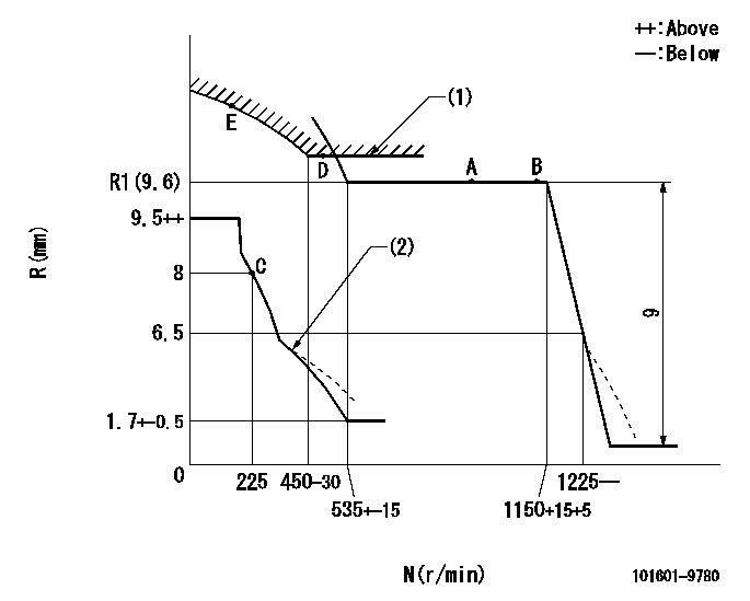
N:Pump speed
R:Rack position (mm)
(1)Excess fuel setting for starting: SXL
(2)Damper spring setting: DL
----------
SXL=R1+0.2mm DL=6-0.2mm
----------
----------
SXL=R1+0.2mm DL=6-0.2mm
----------
Speed control lever angle

F:Full speed
----------
----------
a=10deg+-5deg
----------
----------
a=10deg+-5deg
0000000901
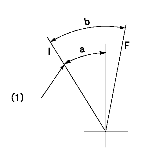
F:Full load
I:Idle
(1)Stopper bolt setting
----------
----------
a=25deg+-5deg b=29deg+-3deg
----------
----------
a=25deg+-5deg b=29deg+-3deg
Stop lever angle
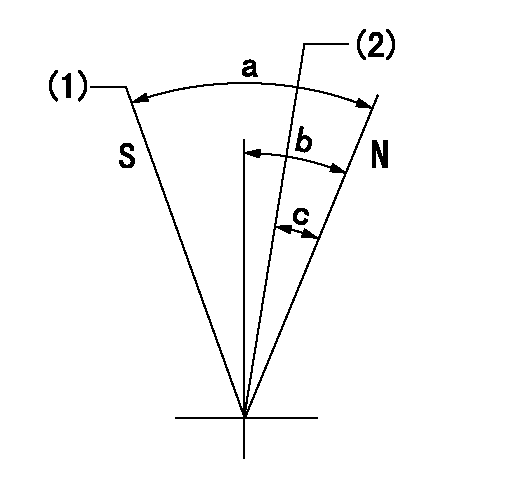
N:Pump normal
S:Stop the pump.
(1)Rack position = aa
(2)Rack position bb
----------
aa=2.5mm bb=21mm
----------
a=71deg+-5deg b=54deg+-5deg c=(9.5deg)
----------
aa=2.5mm bb=21mm
----------
a=71deg+-5deg b=54deg+-5deg c=(9.5deg)
0000001501 MICRO SWITCH
Adjustment of the micro-switch
Adjust the bolt to obtain the following lever position when the micro-switch is ON.
(1)Speed N1
(2)Rack position Ra
----------
N1=325+-5r/min Ra=7.3mm
----------
----------
N1=325+-5r/min Ra=7.3mm
----------
Timing setting

(1)Pump vertical direction
(2)Coupling's key groove position at No 1 cylinder's beginning of injection
(3)-
(4)-
----------
----------
a=(7deg)
----------
----------
a=(7deg)
Information:
AFFECTED PRODUCT
Model Identification Number
C175-20 R4F00100-00120
PARTS NEEDED
Qty
Part Number Description
20 2153198 SEAL-FUEL SYSTEM
20 3618205 SEAL-FUEL SYSTEM
20 3618206 SEAL-FUEL SYSTEM
20 3618207 SEAL-FUEL SYSTEM
20 5272962 CLAMP-INJECTOR
In order to allow equitable parts availability to all participating dealers, please limit your initial parts order to not exceed 32% of dealership population. This is an initial order recommendation only, and the ultimate responsibility for ordering the total number of parts needed to satisfy the program lies with the dealer.
ACTION REQUIRED
Replace the injector hold down clamps in accordance with Disassembly and Assembly, M0067480, "Electronic Unit Injector - Remove" and "Electronic Unit Injector - Install".
Rework the rear heat shields per the attached Rework Procedure.
SERVICE CLAIM ALLOWANCES
Product smu/age whichever comes first Caterpillar Dealer Suggested Customer Suggested
Parts % Labor Hrs% Parts % Labor Hrs% Parts % Labor Hrs%
0-6000 hrs,
0-12 mo 100.0% 100.0% 0.0% 0.0% 0.0% 0.0%
This is a 12.0-hour job
PARTS DISPOSITION
Handle the parts in accordance with your Warranty Bulletin on warranty parts handling.
Rework Procedure
1. Remove the rear 461-6090 and 461-6080 Heat Shields.
Image1.1.1
2. Inspect the inside of the shield for contact with the exhaust log bellows.
Image1.2.1
3. If witness marks are found compress the shield 2 mm at that location using a mallet. Ensure a block of wood is behind the shield when compressing. This operation should be completed with multiple light strikes.
Image1.3.1
4. Reassemble heat shield in reverse order of removal.